PUBLIC WORKS UTILITIES CRITERIA
(PWUC)
For Design & Construction:
Electric, Sewer & Water
NAVFAC MARIANAS (NAVFACMAR) PWUC
Revision 2: 15 November 2018
This PWUC supersedes: PWUC dated 14July2011; Revision 1 dated 02April2015
Page intentionally left blank

NAVFACMAR PWUC
15 November 2018
This PWUC supersedes: PWUC dated 14July2011; Revision 1 dated 02April2015 i
PUBLIC WORKS UTILITIES CRITERIA DESIGN AND CONSTRUCTION: ELECTRICAL,
SEWER, and WATER
Record of Revisions / Changes
Revision #
Date
Description of Changes
1
02 April 2015
Chapter 1, Section 1.2 & 1.4 added sentence to
include AAFB
Chapter 2, Added new Section 2.1.1 – 2.1.1.2
Government Services; Updated Section 2.3.4 –
2.3.4.1 Metering; Added SCADA Section 2.3.7 –
2.3.7.2.3
Chapter 3, Updated Section 3.3.12 Meters; Added
SCADA Section 3.3.15 – 3.3.15.2.3
Chapter 4, Updated Section 4.4.1 Water Meters;
Added SCADA Section 4.5.8 – 4.5.8.2.3
Chapter 5, Replaced with New Chapter 5, Smart
Grid Section 5.1 – 5.2
2
15 November 2018
PWUC - Re-format the whole document, Significant
re-write.
Chapter 1, Updated Section 1.1 – added
“Designers”, changed “encouraged” to “required”;
Updated Section 1.2 to indicate “NAFACMAR Public
Works Utilities on Guam.”; Updated Section 1.3 -
changed “and” to “but it”; Updated Section 1.4 –
clarified that electrical distribution is medium voltage
(not high) and added reference to GUARNG
Barrigada Complex; Updated Section 1.5 – Changed
“Utilities” to “UEM”; Updated Section 1.6 – Complete
re-write (incorporated requirement of previous
sections 1.7 & 1.8); Added/Revised Section 1.7 –
Utilities Connections; Added/Revised Section 1.8 –
Meter Installation & Removal; Added Section 1.9 –
Government Services; Added Section 1.10 – BOSC
Services; Added Section 1.11 – Utility Outages;
Added Section 1.12 – Availability of Utilities for
Contractors; Revised previous section 1.9 – now
Section 1.13 references.
Chapter 2 – Updated Section 2.1 – Changed
“Utilities” to “UEM”, significant re-write – removed
section 2.1.1 (requirement is now in Chapter 1);
Updated Sections 2.3.1.7, 2.3.1.9, 2.3.2.2, 2.3.2.8,
2.3.3, 2.3.4, 2.3.5.2, 2.3.5.3; Added 2.3.5.4 -
“Sectionalizing Termination Cabinet (STC)”; Updated
Section 2.3.7, 2.3.8, 2.3.8.1 and 2.3.8.3; Updated

NAVFACMAR PWUC
15 November 2018
This PWUC supersedes: PWUC dated 14July2011; Revision 1 dated 02April2015 ii
Section 2.3.9.4 - Changed “170 MPH” to “180 MPH”;
Updated Section 2.3.10; Updated Section 2.4 – now
“Equipment, Spare Parts & Special Tools”, remove
previous section 2.4.1 related to “utilities for
contractors”; Updated previous Section 2.4.1.3 &
2.4.1.4 – now section 2.4.1.1 & 2.4.1.2; Updated
Section 2.4.4 and added new Section 2.4.4.1.e;
Updated Section 2.4.13.; Removed section 2.8.
Chapter 3 – Updated Section 3.1.9; Removed
Section 3.1.10 (requirement included in Chapter 1);
Updated Section 3.2.1, 3.2.2, 3.2.13, 3.3.12, 3.3.15,
3.3.17, 3.3.19, & 3.5.2; Removed Section 3.7.
Chapter 4 - Updated Section 4.2.1; Updated Section
4.2.7.2 – Changed “…class 200 (DR 14).” to
“….class 235 (DR 18)”; Updated Section 4.2.8;
Updated Section 4.4.1 – complete rewrite; Updated
Section 4.11 – removed “References”, now
“Construction Notes”.
Chapter 5 – Renamed from “SMARTGRID” to
“COMMUNICATIONS & CYBERSECURITY”;
Significant rewrite
Appendices - Added Appendix 1-7

1$9)$&0$53:8&
1RYHPEHU
)25(:25'
7KLV LV D OLYLQJ GRFXPHQW WKDW ZLOO EH SHULRGLFDOO\ UHYLHZHG XSGDWHG DQG
PDGH DYDLODEOH WR XVHUV DV SDUW RI WKH 1DYDO )DFLOLWLHV (QJLQHHULQJ &RPPDQG
0DULDQDV 1$9)$&0$5 UHVSRQVLELOLW\ IRU SURYLGLQJ WHFKQLFDO FULWHULD IRU GHVLJQ DQG
FRQVWUXFWLRQ SURMHFWV LQ *XDP 'HIHQVH DJHQFLHV VKRXOG FRQWDFW 1$9)$&0$5
IRU GRFXPHQWLQWHUSUHWDWLRQDQGLPSURYHPHQWV
'HYLDWLRQ IURP WKHVH FULWHULD FDQQRW EH PDGH ZLWKRXW SULRU ZULWWHQ DSSURYDO RIWKH
1$9)$&0$58WLOLWLHVDQG(QHUJ\0DQDJHPHQW3URGXFW/LQH&RRUGLQDWRU8(03/&
7KLVGRFXPHQWLVHIIHFWLYHXSRQLVVXDQFH
$87+25,=('%<
61$)$1$06+6+/"56+"*+16
/,216$+6,,/$+1,/666
6
2($6,/'0620$+006$+6
,,/$+1,/666
6
7KLV3:8&VXSHUVHGHV3:8&GDWHG-XO\5HYLVLRQGDWHG$SULO
LLL

NAVFACMAR PWUC
15 November 2018
This PWUC supersedes: PWUC dated 14July2011; Revision 1 dated 02April2015 iv
TABLE OF CONTENTS
CHAPTER 1 - INTRODUCTION ..................................................................................... 1
1.1 GENERAL INFORMATION ............................................................................ 1
1.2 OBJECTIVE ................................................................................................... 1
1.3 PURPOSE AND SCOPE ................................................................................ 1
1.4 APPLICABILITY ............................................................................................. 1
1.5 WAIVER ......................................................................................................... 2
1.6 PROJECT SUBMITTALS ............................................................................... 2
1.7 UTILITIES CONNECTIONS ........................................................................... 2
1.8 METER INSTALLATION & REMOVAL .......................................................... 2
1.9 GOVERNMENT SERVICES ........................................................................... 2
1.10 BASE OPERATING SERVICES CONTRACTOR (BOSC) SERVICES ......... 3
1.11 UTILITY OUTAGES ........................................................................................ 3
1.12 AVAILABILITY OF UTILITIES FOR CONTRACTORS .................................. 4
1.12.1 Paying for Utilities ........................................................................................ 4
1.12.2 Contractor Account / Job Order Numbers .................................................. 4
1.13 REFERENCES ............................................................................................... 5
CHAPTER 2 – ELECTRIC .............................................................................................. 6
2.1 GENERAL INFORMATION ............................................................................ 6
2.2 PRIMARY DISTRIBUTION SYSTEM CHARACTERISTICS .......................... 6
2.2.1 System Voltages ........................................................................................... 6
2.2.2 System Configuration ................................................................................... 6
2.3 EQUIPMENT .................................................................................................. 8
2.3.1 Transformers ................................................................................................. 8
2.3.2 Switchgears ................................................................................................. 10
2.3.3 Relaying ....................................................................................................... 11
2.3.4 Metering ....................................................................................................... 12
2.3.5 Cables .......................................................................................................... 15
2.3.6 Substations (End-of-Line). ......................................................................... 16
2.3.7 SCADA ......................................................................................................... 17
2.3.8 Manholes/Handholes .................................................................................. 18
2.3.9 Overhead Distribution Systems ................................................................. 19
2.3.10 Miscellaneous Equipment .......................................................................... 19
2.4 SPECIFICATIONS ........................................................................................ 20
2.4.1 Equipment, Spare Parts & Special Tools .................................................. 20
2.4.2 Relays ......................................................................................................... 20
2.4.3 Switching ..................................................................................................... 21
2.4.4 High Voltage Cables ................................................................................... 21
2.4.5 Outages ...................................................................................................... 21
2.4.6 Pier (Shore) Power Outlet Assemblies and Cables ................................. 22
2.4.7 Conductors ................................................................................................. 22
2.4.8 Asbestos, Other Environmental Hazards and Personnel Safety ........... 22
2.4.9 Equipment Operation and Maintenance Manuals ................................... 22
2.4.10 Prevention of Damage to Underground Utilities ..................................... 23

NAVFACMAR PWUC
15 November 2018
This PWUC supersedes: PWUC dated 14July2011; Revision 1 dated 02April2015 v
2.4.11 Emergency Eyewash Equipment .............................................................. 23
2.4.12 Warning Signs ............................................................................................ 23
2.4.13 Energization ............................................................................................... 23
2.5 SYSTEM ADEQUACY .................................................................................. 23
2.5.1 Contractor/Designer’s Responsibility ....................................................... 23
2.5.2 System Coordination & Design Analysis .................................................. 24
2.6 DUCT ASSIGNMENT ................................................................................... 24
2.7 TELECOMMUNICATION (INCLUDING TELEPHONE, CATV, AND FIBER
OPTIC CABLES) .......................................................................................................... 24
CHAPTER 3 - SEWER ................................................................................................ 25
3.1 GENERAL INFORMATION. ......................................................................... 25
3.1.1 Subsurface Oil............................................................................................. 25
3.1.2 Existing Underground Utility Lines. .......................................................... 25
3.1.3 Diversion of Sewage/Spills. ....................................................................... 25
3.1.4 Temporary Connections for Contractor Trailers. ..................................... 26
3.1.5 Dewatering into the Sewer Collection System. ........................................ 26
3.1.6 Construction Notes. .................................................................................... 26
3.1.7 Outages. ...................................................................................................... 28
3.2 SEWER LINES. ............................................................................................ 29
3.3 LIFT STATIONS. .......................................................................................... 37
3.4 INDUSTRIAL WASTEWATER DISCHARGE ............................................... 45
3.5 ATTACHMENTS AND FIGURES ................................................................. 46
3.6 Special GWA Requirements for Tie-Ins. ................................................... 63
CHAPTER 4 - WATER ................................................................................................ 64
4.1 GENERAL INFORMATION. ......................................................................... 64
4.2 WATERLINES. ............................................................................................. 66
4.2.9 Cathodic Protection. ................................................................................... 71
4.2.10 Coating for Waterlines under Piers. .......................................................... 71
4.3 WATER VALVES. ........................................................................................ 72
4.3.1 Direction to Open. ....................................................................................... 72
4.3.2 Valve Boxes. ................................................................................................ 72
4.3.3 Corporation Stops for Valves. ................................................................... 74
4.3.4 By-Pass and Gearing. ................................................................................. 74
4.3.5 Butterfly Valves. .......................................................................................... 74
4.3.6 Resilient-Seated Gate Valves. .................................................................... 74
4.3.7 Flange Coupling Adapters. ........................................................................ 74
4.3.8 Anchor Blocks............................................................................................. 74
4.3.9 Service Saddles. ......................................................................................... 74
4.3.10 Backflow Preventers. .................................................................................. 74
4.3.11 Fire Hydrants. .............................................................................................. 75
4.4 WATER METERS. ........................................................................................ 75
4.4.1 Meter Requirements. .................................................................................. 75
4.4.2 Metering Exceptions. .................................................................................. 77
4.4.3 Metering of Lawn Sprinkler Systems. ....................................................... 77

NAVFACMAR PWUC
15 November 2018
This PWUC supersedes: PWUC dated 14July2011; Revision 1 dated 02April2015 vi
4.4.4 Meters 3 Inches and Larger. ...................................................................... 77
4.5 MECHANICAL AND ELECTRICAL EQUIPMENT. ...................................... 77
4.5.1 Equipment. .................................................................................................. 77
4.5.2 Operation and Maintenance (O & M) Manuals. ......................................... 77
4.5.3 Posting of Instructions. .............................................................................. 78
4.5.4 Labeling and Tagging of Electrical Wiring................................................ 78
4.5.5 Training. ....................................................................................................... 78
4.5.6 Special Tool Requirements. ....................................................................... 78
4.5.7 Spare Parts. ................................................................................................. 79
4.5.8 SCADA ......................................................................................................... 79
4.6 MISCELLANEOUS APPURTENANTS. ....................................................... 80
4.7 STORAGE. ................................................................................................... 80
4.8 PUMP STATIONS. ....................................................................................... 83
4.9 WELLS. ........................................................................................................ 84
4.10 CROSS-CONNECTION CONTROL AND BACKFLOW PREVENTION. ..... 84
4.11 CONSTRUCTION NOTES. ........................................................................... 85
CHAPTER 5 - COMMUNICATIONS & CYBERSECURITY ......................................... 86
5.1 OVERVIEW .................................................................................................. 86
5.2 GENERAL REQUIREMENTS FOR ICS ....................................................... 86
5.3 CYBERSECURITY ....................................................................................... 91
APPENDICES:
APPENDIX 1 – FORM - UTILITY CONNECTION PERMIT APPLICATIONS
APPENDIX 2 – INSTRUCTIONS - UTILITY CONNECTION PERMIT APPLICATIONS
APPENDIX 3 – FORMS & INSTRUCTIONS - METER CHANGE RECORD
APPENDIX 4 – FORM - NAVFAC MARIANAS ICS CHECKLIST v2.1
APPENDIX 5 – INDUSTRIAL CONTROL SYSTEM (ICS) BASELINE PROCUREMENT
GUIDANCE v2.1
APPENDIX 6 – FORM - SYSTEM AUTHORIZATION ACCESS REQUEST (SAAR)
FOR INDUSTRIAL CONTROL SYSTEMS (ICS)
APPENDIX 7 – FORM - INFORMATION SYSTEM (IS) PRIVILEGED ACCESS
AGREEMENT AND ACKNOWLEDGMENT (PAA) OF RESPONSIBILITIES

NAVFACMAR PWUC
15 November 2018
This PWUC supersedes: PWUC dated 14July2011; Revision 1 dated 02April2015 1
CHAPTER 1 - INTRODUCTION
1.1 GENERAL INFORMATION
Engineers, Designers and Contractors are required to consult with
NAVFACMAR Public Works Department (PWD) on design and
construction for projects on Public Works Utilities Systems.
Recommended changes and/or deviations to these criteria with supporting
rationale shall be sent to Utilities and Energy Management Product Line
Coordinator (UEM PLC) for review and consideration.
1.2 OBJECTIVE
The purpose of this document is to provide common technical guidance
and to ensure quality and consistency in design and construction for the
NAVFACMAR Public Works Utilities Systems on Guam.
1.3 PURPOSE AND SCOPE
This document prescribes design and construction standards necessary
to support NAVFACMAR Public Works Utilities. It has been developed
from previous “lesson-learned” projects and it is intended for use by
experienced engineers and contractors.
This document does not negate other referenced technical standards and
common industry practices but is provided as additional criteria
specifically for NAVFACMAR Public Works Utilities projects.
This document does not constitute a detailed technical design,
construction, maintenance or operation manual, but it is issued as a
requirement for all NAVFACMAR Public Works Utilities projects.
1.4 APPLICABILITY
This document applies to all designers and contractors preparing design
or performing construction projects involving NAVFACMAR Public Works
Utilities Systems on Guam projects including assets that are under
NAVFACMAR PWD Utilities & Energy Management (UEM) at Navy Base
Guam (NBG), Andersen Air Force Base (AAFB) & Marine Corp Base
Guam (MCBG) (i.e., medium voltage electrical distribution, water
distribution and sanitary sewer systems) and at Guam Army National
Guard (GUARNG) Barrigada Complex (i.e., water distribution and sanitary
systems). Include this document as reference to RFPs.
Designers/Contractor should address any questions to the UEM PLC
regarding applicability for their project.

NAVFACMAR PWUC
15 November 2018
This PWUC supersedes: PWUC dated 14July2011; Revision 1 dated 02April2015 2
1.5 WAIVER
Where a valid need exists and an alternate solution involving sound
engineering and construction is available, designers and/or contractors
can submit request for a criteria waiver to NAVFACMAR PWD UEM.
Requests for waiver should include justification, criteria used, and other
pertinent data.
1.6 PROJECT SUBMITTALS
Provide a minimum of three sets (hard/paper & electronic copies on
optical disc [CD-R or DVD-R]) of design plans (with applicable Basis of
Design, Calculations, Specifications, Response to Comments &
correspondence), Shop Drawings, As-Built plans and Electronic
Operations & Maintenance Systems Information (eOMSI) for review,
comment, acceptance and for record purposes to NAVFACMAR PWD
UEM via Contracting Officer.
Provide As-Built plans & eOMSI submittal to NAVFACMAR Base
Operations Support Contractor (BOSC) technical library & respective
Installation technical library.
Electronic submittals shall include native file formats (Word, Excel, GIS,
AutoCAD, etc.) & pfd.
1.7 UTILITIES CONNECTIONS
The Customer/Customer Representative, Project Manager or Engineer-In-
Charge must contact the UEM as early as in the planning process to verify
the availability of utility services.
Forward the utility connection permit application package (see Appendix 1
& 2 for reference) to the Installation PWD UEM for review & approval.
1.8 METER INSTALLATION & REMOVAL
NAVFACMAR PWD UEM shall be informed of any meter (electric, water &
sewer) installation and removal. Forward the meter change form (see
Appendix 3 for reference) to the Installation PWD UEM for review,
approval & acceptance.
NAVFACMAR UEM Billing & Allocations group shall be informed of the
installation or removal.
1.9 GOVERNMENT SERVICES
Project (MILCON, SRM, Special projects) submittal reviews, facilities
escort, site visits, utility service connections, shall be cost reimbursable

NAVFACMAR PWUC
15 November 2018
This PWUC supersedes: PWUC dated 14July2011; Revision 1 dated 02April2015 3
using project funding, as applicable. Project Manager / Contracting Officer
to coordinate with NAVFACMAR UEM & Financial Management (FM) with
regards to providing funding document & setting up a Job Order Number
(JON).
Escort Services: On occasion, facilities engineering studies/investigations
commissioned by other Navy Activities require others (A-E, outside
consultants or other Navy Personnel) to access secured NAVFACMAR
UEM operational areas (e.g. substation, booster pump facilities, sewer lift
stations, etc.) where qualified NAVFACMAR PWD UEM escorts will be
required. In such instances, the Navy facility sponsor (Project Manager /
Contracting Officer) shall establish a Job Order account with the
NAVFACMAR FM & UEM to reimburse the affected NAVFACMAR PWD
UEM Work Center for escort by qualified maintenance personnel at the
prevailing/established Work Center hourly labor rate. Such escort services
will need to be arranged in advance with the supervisor of the affected
NAVFACMAR PWD UEM Work Center.
The resources of NAVFACMAR PWD UEM or the NAVFACMAR BOSC
shall not be committed to any Project team/Contractor’s work plan without
proper coordination.
1.10 BASE OPERATING SERVICES CONTRACTOR (BOSC) SERVICES
Facilities escort & site visits shall be coordinated with the respective Utility
Annex Contracting Officer Representative (COR) & BOSC Annex
Manager. Project Manager / Contracting Officer to coordinate with
NAVFACMAR UEM & Financial Management (FM) with regards to
providing funding document & setting up a Job Order Number (JON).
1.11 UTILITY OUTAGES
Contractor shall follow provisions in the contract related to utility outage
request.
NBG Utility (Electric, Water & Sewer) outages, De-energization, or
Energization support shall be coordinated with the NAVFACMAR BOSC
Service Support Center. Cost related to Utility service outages /
connections, shall be paid by Contractor to BOSC.
AAFB Utility (Electric) outages, De-energization, or Energization support
shall be coordinated with the NAVFACMAR BOSC Service Support
Center. Cost related to Utility service outages / connections, shall be paid
by Contractor to BOSC.

NAVFACMAR PWUC
15 November 2018
This PWUC supersedes: PWUC dated 14July2011; Revision 1 dated 02April2015 4
AAFB Utility (Water & Sewer) outages support shall be coordinated with
36 CES Customer Service / Operations Support. Cost related to Utility
service outages / connections, shall be paid by Contractor by providing
Job Order Number to Work Center Supervisor when requesting support.
1.12 AVAILABILITY OF UTILITIES FOR CONTRACTORS
Reasonable amount of utilities (normally electricity & potable water) will be
made available to the Contractor at the prevailing rates at the time of use.
Requests for installation of Contractor field offices utility services shall be
forwarded to the Contracting Officer in accordance with the contract
specifications. Request shall include the following information:
a. Site Plan, showing location of Contractor field offices, source/point of
connection of electrical power or water, & proposed route of service
conductors/water line. Plans proposing to route cables in the Navy's
underground distribution system shall indicate the duct(s) to be used.
b. Electric One-Line Diagram, including load (kVA) and voltage
requirements. Meter shall be provided by the contractor.
c. Water One-Line Diagram, including water flow & pressure requirement,
and pipe size. Back flow preventer (BFP) & meter shall be provided by
the contractor.
d. Meter (Electric or Water) & BFP to be used shall be calibrated. Provide
calibration certificate to NAVFACMAR UEM representative.
Calibration certificate shall be effective during the contract duration.
1.12.1 Paying for Utilities
For all construction projects where Government utilities are required for
the Contractor’s use, typically for office trailers, the Navy contractually
requires that the Contractor pay for Government utility service used
(potable water, electricity, sewer, etc.). The Contractor shall also be
responsible for, and pay for, associated costs of connecting,
disconnecting, conveying utilities to the work site, meters, transformers,
backflow preventers, etc. as necessary. Utility billing accounts shall be
established with NAVFACMAR UEM. Coordinate with the Contracting
Officer.
1.12.2 Contractor Account / Job Order Numbers
Contractors performing work shall establish separate job order numbers
with the NAVFACMAR UEM & Financial Management (FM) for the use of
any Navy-supplied electrical, potable water and wastewater provisions
and services to be provided during the construction phase. Such accounts
are usually established through the facilities project / Contract

NAVFACMAR PWUC
15 November 2018
This PWUC supersedes: PWUC dated 14July2011; Revision 1 dated 02April2015 5
administrator. Establish a separate NAVFACMAR Contractor account
(Job Order Number) for required support by Government forces, to
reimburse the affected NAVFACMAR Work Centers for pre-arranged
services, materials and utility consumption. For projects located at the
AAFB, Contractors shall provide Job Order Number to work center
supervisor when requesting support.
Because the primary mission of NAVFACMAR UEM is to ensure reliable
utility services to its customers, Emergency response efforts by
government personnel (including NAVFACMAR BOSC) required to
mitigate a utility emergency situation (i.e. electrical system damage,
sanitary sewage overflows, broken waterlines, etc.) resulting from
construction operations may also be charged to such Contractor accounts.
The resources of NAVFACMAR PWD UEM or the NAVFACMAR BOSC
shall not be committed to any Contractor’s work plan.
1.13 REFERENCES
The “Facilities Criteria (FC)”, “Unified Facilities Criteria (UFC), and “Unified
Facilities Guide Specifications (UFGS)” have valuable information and
requirements relating to subjects that are addressed by these criteria.
Contractor shall comply with the applicable Facilities Criteria (FC), Unified
Facilities Criteria (UFC) and Unified Facilities Guide Specifications
(UFGS) located at http://www.wbdg.org.
If there is a conflict between these criteria and/or other NAVFAC
publications and Government of Guam Standards, the engineer or
contractor shall contact the Contracting Officer or Project Design
Engineer. Where perceived conflicts may exist, the more stringent
requirement will apply. The Contracting Officer or Project Design Engineer
shall contact NAVFACMAR PWD UEM for further guidance.

NAVFACMAR PWUC
15 November 2018
This PWUC supersedes: PWUC dated 14July2011; Revision 1 dated 02April2015 6
CHAPTER 2 – ELECTRIC
2.1 GENERAL INFORMATION
This section covers electrical materials, equipment, and installation
techniques used in general construction for electrical systems to be
maintained by NAVFACMAR PWD UEM.
2.2 PRIMARY DISTRIBUTION SYSTEM CHARACTERISTICS
2.2.1 System Voltages
2.2.1.1 Primary distribution system voltage
Primary distribution system voltage is predominantly and preferred
13.8kV, 3 phase, 3 wire, except in few existing areas with 13.8/7.97kV
and 4.16/2.4kV.
2.2.2 System Configuration
2.2.2.1 Radial Feed - Systems are generally radial in configuration from the main
substations switchgears.
2.2.2.2 Loop Feed - Switches or other means of loop feed capability are required
for new distribution transformers for back feed capabilities.
2.2.2.3 Double Dead Ended with Secondary Tie for Shore Power Stations
2.2.2.4 System Tie Feeders shall not be used to directly supply loads.
2.2.2.5 Dedicated shore power feeders shall not be used to supply non-shore
power loads. Exception: Industrial loads associated with the pier.
Dedicated underground electrical feeders shall provide Shore-to-Ship
power only to ships/vessels. Provide a separate pad mounted transformer
as a source feeder to industrial power at the wharf.
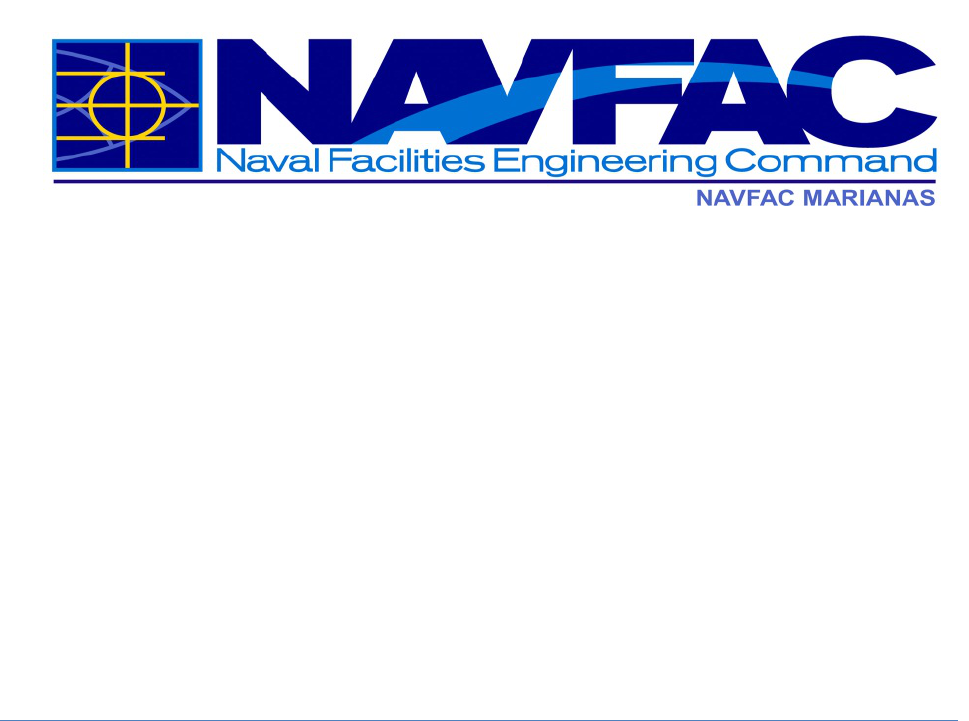
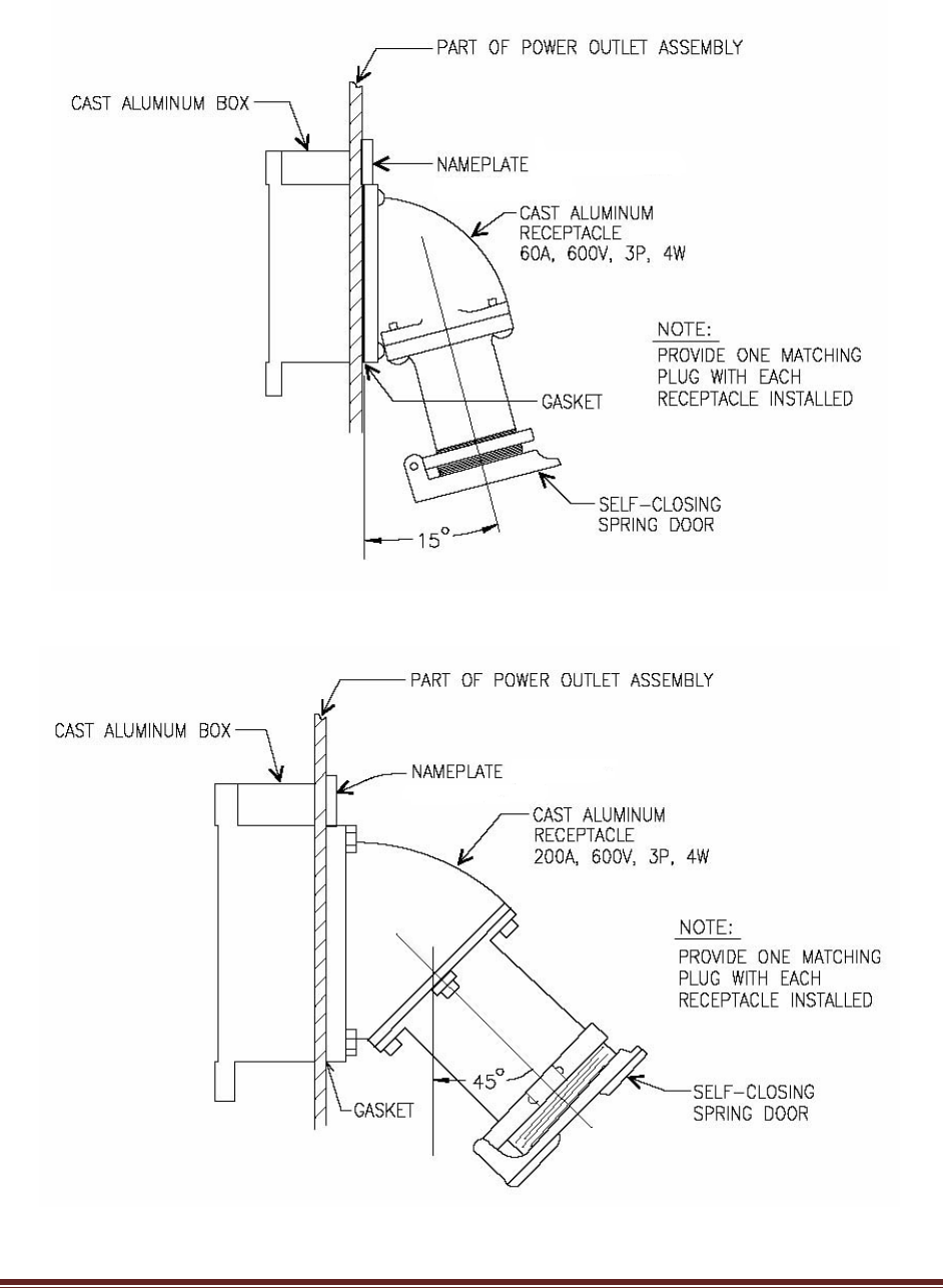
Figure 2-1 shows details for a 60 A industrial receptacle. Figure 2-2 typical
details for a 200 A industrial receptacle.
NAVFACMAR PWUC
15 November 2018
This PWUC supersedes: PWUC dated 14July2011; Revision 1 dated 02April2015 7
Figure 2-1: Typical 60 A Industrial Receptacle
Figure 2-2: Typical 200 A Industrial Receptacle

NAVFACMAR PWUC
15 November 2018
This PWUC supersedes: PWUC dated 14July2011; Revision 1 dated 02April2015 8
2.3 EQUIPMENT
2.3.1 Transformers
2.3.1.1 Size – Distribution transformer size shall be limited to limit the short circuit
current to within economical standard rating of the designed panelboard
size associated with the electrical load. The size limit shall depend upon
the secondary voltage of the transformer. Electrical designs shall include
design analysis and transformer size calculations to be included in the
basis of design and summary of electrical load calculations. Station Class
Power transformers shall be provided with transformer monitor with
SCADA features.
2.3.1.2 Protection
2.3.1.2.1 Primary Protection - All transformers shall be provided with appropriate
primary protective devices, such as fuses, circuit breakers, interrupter
switches, and/or relays, applicable and designed according to the
transformer size.
2.3.1.2.2 Secondary Protection – should not be more than (1.25) X Secondary FLC
or as required by the NEC.
2.3.1.3 Transformer Taps (see section 2.2.1 System Voltages above) - Provide
four 2-1/2 % full capacity primary taps; two above and two below rated
primary voltage.
2.3.1.4 Pad mounted transformer windings shall be made out of copper. Station
class transformer windings shall be made out of copper or aluminum.
2.3.1.5 Transformers shall be insulated with non-PCB mineral oil or other
approved environmentally friendly insulating oil due to recycling and
disposal issues.
2.3.1.6 Submittal Requirements – Designers/Contractors shall submit the
required complete transformer specifications to the NAVFACMAR PWD
Utilities and the Project Design Engineer for review and acceptance prior
to procurement. Transformer data shall include, but not limited to the
following: winding and core materials and design, test data on insulation,
conductors, resistance, dielectric strength, and losses.
2.3.1.7 Pad Mounted Transformers
a. Maximum size – 1000kVA. Transformers rated above 1,000kVA,
serving 480/277 volt loads and above 2,500 kVA serving 480/277 volt
loads must be in a secondary unit substation configuration. On

NAVFACMAR PWUC
15 November 2018
This PWUC supersedes: PWUC dated 14July2011; Revision 1 dated 02April2015 9
upstream of a transformer larger than 1,000kVA, provide pad mounted
VFI switchgear with Tri-phase control devices and complete with
features such as overload, ground and instantaneous fault protection.
The pad mounted VFI switchgear shall be selectively coordinated with
all supply side overcurrent protective devices.
b. Do not use dead front transformers if the available fault current
exceeds 10,000 amperes symmetrical.
c. Constructed of stainless steel.
d. Provide liquid (oil) level indicator.
e. For loop feed systems, provide 3 each two-position load break primary
switches with one set of primary fuses.
f. For loop feed systems supplying single phase transformers, provide
three phase primary switches.
g. For loop feed systems and cable risers, provide auto-resetting,
directional fault indicators for each phase.
h. For loop feed systems, provide cable fault indicator for each phase.
The indicator shall be installed in the out-going side of the loop elbow.
i. Provide test point for the load break elbows.
j. Provide standard fuses instead of current limiting fuses. Exception: For
pad mounted transformers connected directly to 13.8kV radial feeders,
current limiting fuses will be allowed to reduce the available fault
current. Expulsion and Current Limiting Fuse ratings shall be indicated
in the Design Plans and As-Built Drawings.
k. Provide temperature gauge. On transformers over 500KVA, provide
temperature sensor and all communications infrastructure and
integration to the SCADA front end.
l. Provide spare set of fuses.
m. All kWh metering shall be installed on the pad mounted transformer’s
concrete enclosure and not on the transformer’s metal enclosure.
n. Provide bushing mounted elbow type arresters at the end of all radials
and in normally open locations in loops. Provide arresters for all
voltage levels above 5kV.
2.3.1.8 Pole Top Transformers
a. Maximum number of transformers on a single pole shall be three. Limit
pole-mounted transformer sized as follows:
• Three phase installations – limited to three 25kVA transformers or
smaller.
• Single phase installations – limited to one 75 kVA transformer or
smaller.
b. Transformer kVA size shall be labeled on the tank; labels with a
minimum of 4” high lettering.
c. Covers shall be constructed of stainless steel.
d. Provide external tap changer.

NAVFACMAR PWUC
15 November 2018
This PWUC supersedes: PWUC dated 14July2011; Revision 1 dated 02April2015 10
2.3.1.9 Provide transformer identification number on transformer enclosure.
Stencil in 4 inch high white lettering. Transformer ID label shall include the
facility or building number it is feeding, the transformer’s kVA and voltage
rating (e.g. 13.8 kV 480/277VAC)
2.3.1.10 For loop feed systems supplying single phase transformers, identify
transformer phase assignment (i.e. AB, BC, CA) and balance single phase
loads. Provide cable tags identifying phase inside of primary compartment.
2.3.2 Switchgears
2.3.2.1 Breaker Control Voltages
a. Switching Station: 125VDC trip and close
b. Remote or End-of-Line Station (small sizes on isolated areas): use
48VDC or 120VAC trip and close
2.3.2.2 Breaker Indication Lights and Controls
a. Provide the following indication light colors for primary and secondary
power breakers:
1. Green – Normally Open
2. Yellow – Open (Tripped)
3. Red – Normally Closed
b. Indication lights shall be “push-to-test,” transformer, resistor on diode
type.
c. Controls for breakers shall be compatible with existing SCADA
controls and shall be integrated into the SCADA front end. Follow
section 5.
d. Provide each draw out breaker with three position operation. The
connected position and the test/disconnect position shall be clearly
identified by an indicator on the circuit breaker front panel.
e. Provide a portable lifter rated for lifting and lowering circuit breakers
from two-high cubicles. Portable lifter shall have swivel casters in front
for ease of movement.
2.3.2.3 Lightning Arrestors – shall be metal oxide varistor (MOV) type.
2.3.2.4 Busing - Primary and secondary bus shall be copper, fully insulated.
2.3.2.5 Insulators
a. Primary switchgears installed outdoors shall have insulators made of

NAVFACMAR PWUC
15 November 2018
This PWUC supersedes: PWUC dated 14July2011; Revision 1 dated 02April2015 11
porcelain due to Guam environment.
b. Primary switchgears installed indoors shall have insulators made of
porcelain or approved polymer material.
2.3.2.6 Provide bus bar connection from primary switchgear bus to any required
Potential Transformers instead of cable connection due to higher
probability of failure for cable connections.
2.3.2.7 Cable entry into switchgear shall be sealed to prevent rodent entry. All
spare conduit entry into switchgear shall be capped. All entry into
switchgear from manholes shall be sealed in the manhole, including ducts
with cables.
2.3.2.8 Primary Pad Mounted Switches:
a. Provide vacuum bottle technology with appropriate vacuum fault
protection switch. Fault protection relay shall be SCADA ready. Air-
insulated switch is prohibited for corrosive or coastal environment. The
number of switch-ways will be in accordance with the appropriate
design application (depending on the intended system configuration, a
3-way, 4-way, 5-way or at times 6-way switch may be required.
b. Provide key interlock for dual feed system.
c. Require cable fault indicators at switch. The indicators shall be
installed in the out-going side of the loop elbow.
d. Provide type 304L or 316 factory-painted stainless steel enclosure.
e. Provide temporary grounding sets.
f. Switch shall be installed on concrete pad. Seal around opening
between bottom of the switch and concrete pad with sealant or
caulking to resist water, sunlight, and oils.
g. Provide VFI protection device equipped with programmable tri-phase
with ground-trip electronic control logic, relay action indicator or
detector, and port for laptop connection. The device shall be capable of
storing fault events log data. Provide applicable software.
h. Provide high fire point liquid insulation and vacuum bottle interruption,
dead front with stainless steel tanks and operator full size viewing
windows for each way, three position (On/Off/Ground).
i. Provide NEMA ground pad (welded to tank).
2.3.3 Relaying
Provide relaying protections in accordance with the specified guidelines,
standards, and specifications.
2.3.3.1 CT Type - Provide separate CT's for metering (metering accuracy) and
relaying (relaying accuracy).

NAVFACMAR PWUC
15 November 2018
This PWUC supersedes: PWUC dated 14July2011; Revision 1 dated 02April2015 12
2.3.3.2 Installation
a. Meters and relays shall be mounted no lower than 2'-0" from the
bottom of device to floor and no higher than 6'-0" from the top of device
to floor.
b. Meters shall follow section 2.3.4 Metering.
2.3.3.3 Relays shall be microprocessor-based multi-function, programmable type,
capable of communicating directly with the SCADA system, unless
otherwise specified by NAVFACMAR PWD Utilities. If relays being
provided do not already exist in the NFM PWD System, maintenance
instruction/documentation, programmable software, and test instrument
shall be furnished and included as part of the project. Coordinate with
NFM UEM concerning any additional microprocessor-based relay features
or functions available to the device that shall be enabled or activated.
2.3.4 Metering
For each facility or structure that is connected to the NAVFAC Marianas
electrical distribution system, provide a kilowatt-hour and demand meter.
Meters are owned and maintained as a functional part of the electrical
distribution system, as well as the enclosures, switches, cabling, and other
accessories that are critical to meter operation. Low voltage secondary
cables and pathways are owned and maintained as an inherent part of the
facility.
2.3.4.1 The NAVFAC Marianas Advanced Metering Infrastructure (AMI) system is
the required system for utility revenue meters to connect to. The AMI
system uses Modbus/TCP over Cat6 Ethernet and single mode fiber to
network all meters back to centralized servers. New utility revenue meters
are required to be AMI meters, and shall be compatible, programmed, and
integrated with the AMI system in conformance to the AMI system
architecture. All projects that will provide a new AMI meter shall include
the following as part of planning, design, and construction:
a. Installation of new or upgraded OSP fiber optic cable infrastructure
from the nearest NCTS wire center to the facility or structure that is
being metered, as needed, to ensure at least two pairs of single mode
fiber are available for use.
b. Installation of new or upgraded fiber optic cable termination panel,
network switch, enclosure, intrusion detection relay and lock, and
mounting pedestal, at the facility or structure that is being metered, as
needed, to ensure conformance to the AMI system architecture.
c. Installation of new or upgraded AMI meter socket and enclosure,

NAVFACMAR PWUC
15 November 2018
This PWUC supersedes: PWUC dated 14July2011; Revision 1 dated 02April2015 13
intrusion detection relay and lock, network cabling and drops, and
electrical circuit (must homerun to a point upstream of the electrical
meter), as needed, to ensure conformance to the AMI system
architecture.
d. Installation and commissioning of AMI meter, accessories, and all
other AMI equipment, to also include submission of a change request
form, cybersecurity commissioning as outlined in Section 5, delivery of
AMI system inventory and network diagram documentation updates,
and meter changeover documentation required by the NAVFAC
Marianas UEM billing group. Provide wiring with ring lugs for all meter
connections.
Meters shall be socket-type, ANSI class 0.2 or better, and able to
communicate via an optical interface and Modbus/TCP over Ethernet.
Meters shall have at least 32MB of non-volatile memory and shall be
capable of automatically recording consumption data over time using a
configurable time interval (standard setting will be 15-minute interval).
Meters shall have Modbus mastering capability, and shall be capable of
querying water meter RTUs via the network and storing water
consumption and peak flow data over time using a configurable time
interval (standard setting will be 1-hour interval). Meters shall be capable
of measuring delivered kWh energy (delivered, received, net) and
delivered kW demand (instantaneous, cumulative, peak), kVARh/kVAR,
kVAh/kVA, PF (min, instantaneous, average), harmonic measurements
(%THD voltage and current), voltage quality measurements (sags, swells,
imbalances), and shall be capable of detecting and recording events for
the conditions of voltage sags and swells, low power factor, high
harmonics, high neutral current, hardware/memory failure, low battery,
and wiring errors (e.g. reverse rotation on any phase). Meters shall also
be equipped with digital input and output capability (e.g. KYZ pulse, relay).
Meter data and programming shall conform to the latest “AMI to MDM Call
for Consistency” document and shall be programmed and integrated to be
capable of automated remote reading. Submit a request for NAVFAC
Marianas UEM to provide Device ID, Meter Point ID, and IP
address/subnet mask/default gateway, prior to programming/configuration.
Request must include project name, work description, ready-for-
construction (RFC) site plan and one-line schematic.
Meter enclosures (and enclosures for associated equipment) shall be
located on the facility exterior wherever possible, in a location that will
ensure that utility personnel are able to freely access utility meters and
their respective enclosures. If a suitable wall is not available for mounting
AMI equipment, a reinforced concrete utility pedestal shall be provided to
mount all necessary AMI equipment. Provide reinforced concrete bollards
to prevent vehicle damage to AMI equipment if it is located such that it is

NAVFACMAR PWUC
15 November 2018
This PWUC supersedes: PWUC dated 14July2011; Revision 1 dated 02April2015 14
susceptible to damage caused by vehicle traffic, but do not place bollards
in such a way that access to the enclosures and equipment is limited. All
enclosures shall be capable of being secured via padlock, and shall be
rated NEMA 4X stainless steel grade 316 or better, except that socket
enclosures are permitted to be NEMA 3R stainless steel grade 304. Equip
enclosures with molybdenum alloy stainless steel padlocks, common
keyed to match existing. Provide surge protection devices and grounding
as needed to protect AMI devices, accessories, and communications
pathways. Provide a door sensor on the interior of each enclosure, to be
wired as a digital input for intrusion detection purposes.
Provide test switches (ten-pole blocks) equipped with shorting bars (to
prevent “open secondary” for current transformers), to enable technicians
to remove the meter from the circuit for testing/maintenance purposes
without effecting an outage. Provide wiring and cabling that is color coded
in accordance with the latest applicable UFGS for electrical metering (26
27 14.00 20 at the time of this writing). Wiring must also be
marked/labeled at both ends, in a way that is easily correlated with project
record drawings. All wiring shall be performed in a professional manner
with wire bundled and supported.
Coordinate all meter installations with the BOSC. The installer and the
BOSC shall ensure that meter changeover information is properly
documented at the time of any meters being changed out, using a form to
be provided by NAVFAC Marianas UEM. Facility owner/activity must be
identified properly on the form to ensure recording for billing purposes.
Electrical metering characteristics after the changeover shall be verified to
determine if any possible wiring errors or equipment malfunctions have
occurred and (if any) shall be resolved at the time of the changeover.
Provide complete manufacturer documentation including installation,
maintenance, testing, and user manuals. Manufacturer documentation
shall also be provided for all other provided devices, accessories, and
software.
If provided meter is not directly supported by the manufacturer for the
existing AMI system front-end software (Schneider Electric ION
Enterprise), provide software drivers that will enable the AMI system
software to remotely interface with the provided meters, and to
automatically retrieve meter data. Software drivers shall become property
of the Navy, or shall be licensed to the Navy for unlimited utilization within
the Navy. Turn over the source code and original files for all scripts,
drivers, and/or configuration files that are created for the fulfillment of the
project, and the Navy shall retain full ownership and all rights for such
documents. AMI system access requirements and restrictions for
personnel performing software integration work are given in Section 5.

NAVFACMAR PWUC
15 November 2018
This PWUC supersedes: PWUC dated 14July2011; Revision 1 dated 02April2015 15
Requirements for network devices and pathways are given in Section 5.
2.3.4.2 CT Type
a. Provide separate solid core CT's for metering (metering accuracy, +/-
0.3% or better) and relaying (relaying accuracy). Split core CT is not
acceptable.
2.3.4.3 Installation
a. Meter base shall be mounted approximately 4’-0” from the floor.
Switchboard type meters shall be mounted no lower than 2'-0" from the
bottom of device to floor and no higher than 6'-0" from the top of device
to floor.
2.3.5 Cables
2.3.5.1 Splicing Method and Material Restrictions
a. For heat-shrinkable joints: Do not use this method in an oil-
contaminated manhole.
b. Primary cable splices shall be made only in electrical manhole not
handhole.
2.3.5.2 Size
a. 500 kcmil copper: Distribution.
b. EPR, 15 kV, 133% UGN application, 5 mil, 25% overlap tape shield.
c. Single conductor
d. Provide counterpoise ground wire with all underground installations.
e. Provide complete grounding system in all underground electrical
structure installations.
2.3.5.3 Installation in Manholes
a. Do not install more than 8 primary cables in one manhole.
b. Recommend do not install more than 2 circuits in one manhole.
c. Do not completely loop primary cables in congested manholes.
Provide sufficient slack in cables for 1 set of splices.
d. Provide phenolic cable nameplates/tags (1/16” thick) secured by nylon
tie wrap for primary and secondary cables. Nameplates shall be
engraved with yellow background and black letters (1” high). Cable

NAVFACMAR PWUC
15 November 2018
This PWUC supersedes: PWUC dated 14July2011; Revision 1 dated 02April2015 16
tags shall include the circuit ID number, system voltage, phase, cable
size, “from” where it originates and “to” where the cable goes.
e. Underground conduits shall be a minimum of 6” along main run
between underground structures (for Air Force, conduits may be a
minimum of 5”).
f. Ductbanks shall be reinforced for seismic conditions.
g. There shall be no separate splices, Bolted-T connections or load
junction in a primary electrical manhole.
2.3.5.4 Sectionalizing Termination Cabinet (STC)
a. Provide STC instead of separable (Y or Bolted-T) splices.
b. Provide pad-mounted, dead-front sectionalizing termination cabinets,
600 Amps, 3 phase, 15kV, 600 Amps dead-break/200 Amps load-
break bushings, 95kV BIL in IEEE C57.12.28 compliant stainless steel
enclosures. Provide high profile sectionalizing termination cabinets
when the conductor size is larger than 4/0 AWG to meet the cable
bending radius requirement. Install fault indicators on all outgoing
circuit feeds.
c. The STC’s bushing center point shall be at a minimum height of its
concrete pad finished grade. Low profile STC is not recommended.
d. Provide cable fault locator to each phase of the outgoing (lateral)
cables.
e. New fault indicators shall be intended for underground application trip
level selection with auto adjusting, fault sensing range from 50 to
1200A, and minimum operating current of 3A. Provide battery powered
fault indicator for lines with less than 3A load current. Self-powered
fault indicators shall be provided for all main feeders and battery
powered fault indicators shall be provided for branch lines to
transformers.
f. Provide tags for all underground cables in all accessible locations such
as in manholes, transformers, switchgear and sectionalizing
termination cabinet.
2.3.6 Substations (End-of-Line).
Provide complete grounding system in all underground electrical structure
installations.
2.3.6.1 For new stations, provide 2 incoming primary circuits with individual
overcurrent protection.
2.3.6.2 Always provide CLF's for fused primary switches.

NAVFACMAR PWUC
15 November 2018
This PWUC supersedes: PWUC dated 14July2011; Revision 1 dated 02April2015 17
2.3.6.3 New Substation Buildings
a. At a minimum, provide 4" C to nearest MH for future telephone,
SCADA requirements, unless otherwise specified in the project
specifications. Provide communications pathway to the SCADA front
end. New substation control systems shall follow section 5.
b. Provide door hasp for substation security; NAVFACMAR PWD Utilities
will furnish its own padlock.
c. Provide double doors for all entry points.
d. Provide primary and secondary power cable trench from point of
substation entry and between primary switchgear, transformer and
secondary switchgear. This will allow installation and replacement of
cables with less effort. Cables in trench shall be fireproofed and
supported.
2.3.6.4 For outdoor substations with separate primary switchgear install a cable
(instead of bus) connection between the transformer and primary
switchgear.
2.3.6.5 Secondary Main Breaker Section:
a. Require an individual breaker section, separate from secondary
switchboard, to be provided. The purpose of the section is to establish
a demarcation point to identify the ownership between NAVFACMAR
PWD Utilities and customer.
b. Require a draw out type breaker with solid-state trip device.
2.3.7 SCADA
2.3.7.1 When adding new SCADA components, the new components shall be
compatible with and integrated for operation under the existing Navy
Electrical System SCADA system. New remote SCADA components shall
connect and be integrated to the central control station front end. The
communication medium shall be fiber unless a waiver is received from
Utilities. Communications and requirements for cybersecurity shall follow
section 5. At a minimum, monitoring points shall include frequency,
voltage, current, power, power factor, intrusion detection, and breaker
status. Logging of these point’s values shall occur at a minimum of 15
minute intervals. Control shall allow operation to open and close breakers
remotely from the front end.
Contractor integrating new remote with existing master shall have the
following (or equal) qualifications:
a. Certified by master station software vendors as “qualified” via
attendance in formal training classes, etc.

NAVFACMAR PWUC
15 November 2018
This PWUC supersedes: PWUC dated 14July2011; Revision 1 dated 02April2015 18
b. Minimum 3 years of experience integrating specific remote equipment
(RTU, Automation Controller, etc.) with existing master.
It is not acceptable for the Contractor to claim a status of “qualified” by
taking master station software training classes after contract award.
The project shall include the following general requirements:
a. On-site training for Engineers and O&M personnel.
b. Factory training if necessary.
c. Site specific documentation (schematics, wiring diagrams, training
documentation, user & troubleshooting manuals, etc.).
d. Configuration of master to remotely monitor/control new remote points
and historize as necessary.
e. Creation of new remote station one-line diagrams and reports in
master station HMI as necessary.
f. Site Acceptance Testing (SAT) and Factory Acceptance Testing (FAT),
if deemed necessary.
g. New remote equipment (RTU, Automation Controller, etc.) shall have
at least 50% expansion capability fir additional points.
h. New equipment spare parts.
When providing and integrating Intelligent Electronic devices (IEDs),
include the following:
a. Logic diagrams with accompanying narratives.
b. IEDs configuration files.
c. IEDs Front Panel Faceplate display in master station HMI for each
IED. This IED HMI faceplate shall display the correct status (ON/OFF)
of each IED Target LED.
2.3.8 Manholes/Handholes
2.3.8.1 For new manholes/handholes:
a. Provide a manhole cover with the word “ELECTRIC” stamped in the
center. Bond manhole cover with a minimum 6 AWG conductor to the
manhole ground loop.
b. Prevent surface water entry by elevating entry opening above
surrounding terrain except in sidewalks. Manholes/handholes are not
allowed in roadway areas. Underground electrical lines shall not be
designed within the roadway areas unless the electrical line’s crossing
is required for tie-in and/or completing the design for the service area.
c. Coat exterior walls to prevent infiltration of liquids such as water and
oil.
d. Provide closed sump if located below sea level or in liquid (water, oil,
etc.) saturated soil. Otherwise, provide open sump.

NAVFACMAR PWUC
15 November 2018
This PWUC supersedes: PWUC dated 14July2011; Revision 1 dated 02April2015 19
e. Seal all ducts entering manhole/handhole.
2.3.8.2 For new manholes/handholes, provide:
a. An identification number embedded on the manhole rim on at least four
different locations.
b. Manholes, sized accordingly to provide adequate space for personnel,
cables and future requirements. Minimum size of manhole shall be in
accordance with applicable UFC standards, unless otherwise specified
in the contract specifications or by NAVFACMAR PWD Utilities.
2.3.8.3 For new handholes, provide concrete covers to prevent unauthorized
access. For medium voltage handholes with concrete cover, provide ID
labels engraved onto the concrete frame or concrete cover. Minimum size
of handhole shall be of 4’ x 4’ x 6’; unless otherwise specified by
NAVFACMAR PWD Utilities.
2.3.9 Overhead Distribution Systems
2.3.9.1 Fuse cutouts shall be load break cutouts and made of porcelain material.
2.3.9.2 Do not connect to existing primary overhead lines using a mid-span tap
and slack span for the following reasons:
a. Lower strength of connection, especially during poor weather
conditions.
b. Our shops normally do not stock the connectors for mid-span taps.
c. A higher probability that the primary line must be de-energized for
maintenance and repair due to the slack span.
2.3.9.3 Minimum size of new primary lines shall be #2 (solid).
2.3.9.4 Poles shall withstand the 180 MPH wind speed and loading criteria.
2.3.9.5 Minimum diameter for pole ground rod shall be 3/4” diameter X 10’ length
and made of copper clad steel.
2.3.10 Miscellaneous Equipment
2.3.10.1 Heaters
a. Heater for primary and secondary switchgear is required.
b. Heaters must be operational after the switchgear is installed, before
and during commissioning. Heaters shall have thermostatic control and
shall have automatic control features.

NAVFACMAR PWUC
15 November 2018
This PWUC supersedes: PWUC dated 14July2011; Revision 1 dated 02April2015 20
2.3.10.2 When retrofitting existing equipment, the design shall provide the
nameplate data.
2.3.10.3 Installation of Equipment Not Owned by NAVFACMAR PWD Utilities.
Equipment not owned by NAVFACMAR PWD Utilities shall not be located
in, attached to or consuming electrical power from NAVFACMAR PWD
Utilities electrical facilities (substations, switching stations, etc.). If this is
not possible the owner of the equipment shall submit a written request to
NAVFACMAR PWD Utilities explaining why alternative equipment location
is not possible. If the request is approved:
a. The equipment shall be tagged clearly identifying the owner.
b. NAVFACMAR PWD Utilities reserves the right to remove or relocate
the equipment
c. We may require the installation of a kWh meter for electrical billing
purposes.
d. If electrical service is supplied from a panel board in the facility, the
equipment owner will have to depend on NAVFACMAR PWD Utilities
forces to allow access into the facility for resetting the panel board
circuit breaker, etc.
2.4 SPECIFICATIONS
2.4.1 Equipment, Spare Parts & Special Tools
2.4.1.1 All equipment containing dielectric fluid shall be accompanied by the
manufacturer's certification that the equipment contains no detectable
PCB's or that the PCB level is less than 1 PPM, IAW OPNAVINST
5090.1A (Environmental Natural Resources Program Manual) dtd 2 Oct
90.
2.4.1.2 Provide spare parts and special tools for equipment to be provided under
contract - fuses, circuit breaker test set, tools, protection relay test kit, etc.
2.4.2 Relays
2.4.2.1 Testing
a. Relay Wiring Testing: Testing and verification of CT ratio and polarity
and relay operation shall be done by primary current injection.
b. Differential protective relaying circuits shall be tested under load in
addition to the primary current injection testing.
2.4.2.2 Time-Current Curves: Submit original manufacturer's published time-
current curves of transformer fuses, secondary breakers, relays, etc. for
application of relay settings.

NAVFACMAR PWUC
15 November 2018
This PWUC supersedes: PWUC dated 14July2011; Revision 1 dated 02April2015 21
2.4.3 Switching
Only the BOSC Utilities Electrical Power Distribution personnel are
authorized to perform switching. Do not use the term "de-energize".
2.4.4 High Voltage Cables
2.4.4.1 Hi-Pot Testing
a. Conduct the tests in three phases: 1) For the existing conductors,
2) For the new conductors after installation, splices and
terminators/connectors and before terminating to equipment or splicing
to existing conductors, 3) For any of the combined new and existing
conductors or new terminators/connectors and existing conductors.
b. New Cables: Perform field acceptance tests on new cables in
accordance with ANSI/NETA ATS and IEEE 400.2. Tests must be
shield continuity test, insulation resistance test and very low frequency
(VLF) alternating voltage withstand test/Hi-Pot for a duration of 60
minutes using a sinusoidal waveform.
c. Existing Cables/Existing cables connected to new connector,
terminator and or new cables: Perform field maintenance tests on
combined existing cables, new connector, terminator and or new
cables in accordance with ANSI/NETA MTS and IEEE 400.2. Tests
must be insulation resistance test and very low frequency (VLF)
alternating voltage withstand test/Hi-Pot for a duration of 30 minutes
using a sinusoidal waveform.
d. Furnish a copy of Hi pot test report certified and signed by the
Contractor and DOR to NAVFACMAR PWD Utilities for review and
comments upon completion of testing.
e. Label all medium voltage cables – Tags or labels shall include the
voltage rating, phase size of cable, circuit identification, and “to” and
“from” information. Cable tags shall be in conformance with UFC and
UFGS criteria.
2.4.5 Outages
2.4.5.1 Electrical outages shall be requested in writing in accordance with the
contract requirements.
2.4.5.2 Electric Power Generator support for scheduled electrical outages on
critical facilities (including housing) due to construction contract work shall
be provided by the Contractor.

NAVFACMAR PWUC
15 November 2018
This PWUC supersedes: PWUC dated 14July2011; Revision 1 dated 02April2015 22
2.4.6 Pier (Shore) Power Outlet Assemblies and Cables
2.4.6.1 Insulation resistance readings for 600 volt class shore power cables shall
not be less than 100 mega ohms.
2.4.6.2 Single conductor, 600A pier receptacles shall meet standard configuration.
2.4.6.3 Each pier receptacle shall be 400A minimum load tested as a complete
system for a period of not less than 4 hours. NAVFACMAR PWD will not
provide the load bank to load test the pier receptacles. Power required to
load test shall be charged to the Contractor.
2.4.7 Conductors
2.4.7.1 All conductors (primary and secondary) including equipment buses,
transformer windings, etc. shall be made of copper subject to UFC 3-550-
01 Par 3-11.1 restrictions.
2.4.8 Asbestos, Other Environmental Hazards and Personnel Safety
2.4.8.1 NAVFACMAR PWD Utilities has information on the removal of asbestos
fireproofing on primary cables in manholes. However, the designer is still
required to field verify conditions.
2.4.8.2 NAVFACMAR PWD Utilities is not responsible for ensuring a safe working
environment in manholes. Therefore, NFM is not responsible for testing for
and removing asbestos, water, oil and oily water from manholes in support
of a construction contract. Provide dewatering in accordance with
approved waste water disposal plan.
2.4.8.3 All Contractors shall coordinate entry into manholes and substations with
BOS Contractor via the Contracting Officer for the project. Cost associated
with the support of the BOS Contractor shall be charged to the
Construction Contractor.
2.4.9 Equipment Operation and Maintenance Manuals
2.4.9.1 NAVFACMAR PWD Utilities requires a minimum of three bound manuals
and one digital version for new equipment. If new equipment is to be
installed at multiple substations/locations, then the manuals shall be
separated and identified by substation/location.
2.4.9.2 Submit the O&M manuals to NAVFACMAR PWD Utilities prior to start of
acceptance (walk thru) inspection.

NAVFACMAR PWUC
15 November 2018
This PWUC supersedes: PWUC dated 14July2011; Revision 1 dated 02April2015 23
2.4.10 Prevention of Damage to Underground Utilities
2.4.10.1 Although clearances are issued by the BOSC, toning prior to any
excavation is highly recommended. Contractor shall refrain from utilizing
mechanized heavy equipment when excavating near known underground
utility lines. Excavation should be performed by means of hand-held tools
(e.g., shovel and pick) or small power tools. When hand-held power tools
are utilized, extreme care must be practiced to avoid causing damage to
any existing underground utility lines.
2.4.11 Emergency Eyewash Equipment
2.4.11.1 Emergency eyewash equipment shall conform to ANSI Z358.1 (Plumbed
and Self-Contained Eyewash).
2.4.12 Warning Signs
2.4.12.1 Provide warning signs for new substations with equipment ratings that
exceed 600 volts as required by ANSI Z35.1. Metal signs with the legend
“DANGER HIGH VOLTAGE KEEP OUT” shall be provided in three lines of
nominal 3-inch high letters and installed on the exterior walls (front, sides
and rear) of the pad mounted equipment concrete enclosure.
2.4.13 Energization
Field test of all equipment (transformer, switchgears, cables, and other
testing requirements results) shall be performed in accordance with the
contract specifications. Contractors and Electrical Designer of Record
shall certify and sign the test results and provide to NAVFACMAR PWD
Utilities and the Project Design Engineer for review and acceptance.
Copy of test results shall be provided to BOSC for review prior to
energization date.
Field inspection to the new electrical equipment and any existing
equipment affected by the construction work shall be performed prior to
energization. PWD UEM/BOSC Utilities Engineering shall be informed in
advance concerning any scheduled electrical utility inspection.
2.5 SYSTEM ADEQUACY
2.5.1 Contractor/Designer’s Responsibility
It is the Contractor/Designer's responsibility to evaluate & ensure that the
existing electrical system can accommodate any proposed increase in
load. If the existing electrical system cannot accommodate the proposed
increase, Contractor/Designer shall include in the design any necessary
upgrades to accommodate the increase in load. Cost of upgrades shall be
funded by the proposed project. Coordinate with NAVFACMAR UEM.

NAVFACMAR PWUC
15 November 2018
This PWUC supersedes: PWUC dated 14July2011; Revision 1 dated 02April2015 24
2.5.2 System Coordination & Design Analysis
System coordination study and design analysis, recommended ratings,
and settings of protective devices shall be accomplished by a registered
professional electrical engineer with a minimum of 5 years of current
experience in the coordination of electrical power systems. The complexity
and extent of the study is dependent on the work required (e.g. type and
load of facility addition, reconfiguration or replacement of utility
infrastructure, etc.). It is the Contractor/Designer's responsibility to ensure
that the protective devices specified for any project coordinate properly
with any existing upstream/downstream protective devices.
2.6 DUCT ASSIGNMENT
2.6.1 The identifying, routing and assignment of ducts will be the Design
Engineer's responsibility.
2.6.2 NAVFACMAR PWD Utilities requirements are summarized below:
a. Verifying the existence and serviceability of existing ducts is the
responsibility of the requesting party.
b. The last spare duct in each duct section is reserved for emergencies,
and therefore is not available for use.
2.7 TELECOMMUNICATION (INCLUDING TELEPHONE, CATV, AND
FIBER OPTIC CABLES)
Designers/Contractors shall coordinate design and construction with the
respective telecommunication owners, unless otherwise specified in the
projects’ specifications.
Designers/Contractors shall provide the necessary ducts and fiber optic
cables/connections for the appropriate Industrial Control System (e.g.
DDC, SCADA, AMI) required to be installed and shall follow section 5.

NAVFACMAR PWUC
15 November 2018
This PWUC supersedes: PWUC dated 14July2011; Revision 1 dated 02April2015 25
CHAPTER 3 - SEWER
3.1 GENERAL INFORMATION.
This section covers general information for sewer facilities including
wastewater distribution and lift station systems, as applicable.
3.1.1 Subsurface Oil.
When performing excavations in areas where oil may be encountered,
include appropriate construction/contract provisions to address the
handling and disposal of the oil as necessary and to prevent the inflow of
this ground oil into the sewer collection system from construction activities.
3.1.2 Existing Underground Utility Lines.
Plans and specifications shall require the toning of any area to be
excavated for underground utility lines. In areas where non-metallic pipe
lines may be present, ultrasonic detection methods or field-locating grade
nodes (manholes, cleanouts) may be used as appropriate. Gravity sewer
alignments and depths can generally be determined from open
inspections of existing grade provisions (manholes and cleanouts).
Ground Penetrating Radar (GPR) systems shall be used prior to
excavation in all Shipyard areas. Research “as-built” construction
drawings, and perform field investigations, to ensure that all known
underground utility lines are identified on the construction drawings prior to
actual field excavations. Perform soil borings sampling and testing when
required. Include a note and/or specification to indicate the cost of
repairing any damaged underground utility line shall be borne by the
Contractor regardless of whether or not the utility lines are depicted on the
construction drawings.
3.1.3 Diversion of Sewage/Spills.
Plans and specifications shall require the Contractor to be responsible for
diverting sewage as necessary for performance of work. The Government
will not perform sewage diversion operations for the Contractor however
will provide an end point for sewer disposal. The Contractor shall supply
all labor and equipment necessary to compliantly perform his operations
which may include the use of bypass pumps, tank trucks, temporary
piping/hoses, etc. The Contractor will also be responsible for any sewage
spills and regulatory fines resulting from construction operations. See
section 3.1.7 for outages.

NAVFACMAR PWUC
15 November 2018
This PWUC supersedes: PWUC dated 14July2011; Revision 1 dated 02April2015 26
3.1.4 Temporary Connections for Contractor Trailers.
Any Contractor requiring a temporary sewer connection shall submit a
request to perform work on the Navy’s sewerage system with plans or
sketches to NAVFACMAR BOSC for review and approval prior to making
the connection (see section 3.5.1). The Contractor is responsible for
metering utility consumption for billing purposes. The submittal should be
made through the Contracting Officer or facilities Project Manager as
appropriate. Upon completion of the work, the Contractor shall terminate
the connection as prescribed by NAVFACMAR BOSC. Onsite
Government inspection may be required. Abandoned temporary
connections with open cleanouts are not allowed.
3.1.5 Dewatering into the Sewer Collection System.
Construction dewatering into the Navy’s sewer collection system is not
permitted. Batch discharges of other types of wastewater into the Navy’s
sewer collection system require case by case approval by NAVFACMAR
EV. Discharges of hydro-test water, dechlorinated water from pipe line
disinfection and flush water from storm drain cleaning is not permitted into
the Navy’s wastewater collection system. These are considered to be non-
industrial wastewaters that can be disposed of by means other than by
discharge into the domestic sewer collection system.
3.1.6 Construction Notes.
Construction drawings should include pertinent project-specific sewer
notes or construction notes to clarify or bring attention to certain
construction requirements that directly or indirectly affect the Navy’s sewer
collection/transmission systems and those who work on these systems.
Some of the following sewer notes may apply to typical sewer construction
work. The designer may choose to modify these notes and/or provide
other project-specific notes as deemed applicable to the scope of work.
a. The Contractor shall be responsible for performing and maintaining
any incidental sewage bypass pumping or diversion work that will be
required to accomplish the construction work.
b. For any new concrete surface that will be exposed to sewage flow, the
Contractor shall maintain sewage bypass/diversion operations for the
duration of the specified curing time for the concrete.
c. The Contractor shall be responsible for providing and maintaining
temporary power as necessary to maintain normal lift station
operations.
d. The Contractor shall be responsible for damage to any Government
utility system resulting from construction operations; any damage shall
be reported immediately to the Contracting Officer or appropriate
Government Representative. Any sewer repair performed by the

NAVFACMAR PWUC
15 November 2018
This PWUC supersedes: PWUC dated 14July2011; Revision 1 dated 02April2015 27
Contractor shall be inspected by the NAVFACMAR PWD Utilities via
the Contracting Officer’s representative prior to backfilling.
e. The Contractor will be responsible for regulatory fines or penalties that
may be imposed by environmental regulatory agencies (NAVFACMAR
EV and/or EPA) in the event of sewage overflow or spill resulting from
construction operations.
f. The Contractor shall reimburse the Government for any emergency
response effort that may be required by Government forces to mitigate
the adverse effects of any sewage overflow or spill resulting from the
Contractor’s operations.
g. Any sewer manhole to be abandoned shall have its cone section
removed and disposed of, pipe penetrations plugged with Class “C”
concrete and the remaining riser structure backfilled and compacted to
finish grade.
h. Cleanouts on any abandoned service lateral shall be plugged and
terminated a minimum of 12 inches below finish grade.
i. Prior to abandonment, pipe shall be filled with flowable fill as noted.
j. The Contractor shall contact NAVFACMAR BOSC Wastewater
Manager (phone: 339-1794) via the Contracting Officer’s
representative to make arrangements for the Government to take
custody of salvageable sewer manhole frames and covers. Manhole
frames and covers not accepted by the Government shall be disposed
of by the Contractor.
k. When working on dockside or under pier ship wastewater collection
system piping, the Contractor shall first mechanically secure and tag
out hose connections along the entire length of the common pressure
manifold prior to working on the system.
l. Potentially lethal levels of hydrogen sulfide (H2S) gas may develop in
the gravity sewer collection system.
m. The Contractor shall ensure that loose material, tools and equipment
from construction operations are appropriately removed from the sewer
collection system. Any damage to downstream lift station equipment
resulting from negligence will be assessed to the Contractor.
n. Prior to securing potable water outages in mains or service
connections, the Contractor shall first provide and maintain a backup
seal water provision to lubricate pump seals at the affected sewer lift
station shown on the plans. Coordinate access to the affected lift
station, at least 3 days in advance of the outage, with the
NAVFACMAR BOSC Wastewater Manager (phone: 339-1794) via the
Contracting Officer’s representative.
o. Adjust all manhole frames and covers to the new finish grade and
ensure the adjustments prevent surface runoff inflow. Mark all covers
as SEWER.
p. Provide 3 days advance notice to NAVFACMAR PWD Utilities via the
Contracting Officer, for joint ROICC or FEAD/NAVFACMAR PWD

NAVFACMAR PWUC
15 November 2018
This PWUC supersedes: PWUC dated 14July2011; Revision 1 dated 02April2015 28
Utilities inspection of any new wye saddle construction for new service
connections to existing sewer mains.
q. During periods of non-work and for the duration of contract work within
the secured perimeter of the lift station, the Contractor is responsible
for securing access gates, doors and security. After normal working
hours, the Contractor is responsible for properly securing access
gates, doors and security fencing.
r. Upon completion of the sewer construction, make advance
arrangements (3 working days minimum), through the Contracting
Officer’s representative, with NAVFACMAR PWD Utilities
Water/Wastewater Superintendent (phone: 339-2397) for final
acceptance inspection of the new sewer construction.
s. Construction dewatering into the Navy’s sewer collection system is
prohibited.
3.1.7 Outages.
As much as possible, sewage flow shall not be interrupted. Contractor-
provided bypass measures should be incorporated into the design of the
project. When brief outages will be required at sewage lift stations for
work involving motor controls, control valves and pressure mains, the
designer should determine a reasonable outage period based on available
engineering information. The designer should also coordinate construction
requirements with the NAVFACMAR BOSC Wastewater Manager (phone:
339-1794). The ideal time for lift station outages would be during low-flow
periods, normally at midnight. The designer should, during the design
phase, discuss the details of such planned outages with the Lift Station
section Supervisor. In rare situations, Government forces may be
required to assist the Contractor by securing operational controls during
the outage period. Such Government services will be charged to a pre-
established and cost-reimbursable Contractor or project-sponsor job order
account and shall be arranged/planned in advance with the NAVFACMAR
BOSC. For lift station outages, the Contractor should also plan for and
provide standby emergency contingencies, to prevent system overflows
(Contractor’s responsibility). Contractors shall provide and maintain
interim emergency generators or portable pumping provisions to maintain
normal sewage flow as needed to perform the work.
3.1.8 Requests for Information from Government Contractors and Outside
Parties.
All requests for information on the Navy’s wastewater system by
Government Contractors and other outside parties shall be made via the
cognizant Navy Contract Administrator, Project Design Engineer,
Program/Project Manager or responsible Navy Facilities Representative
who will validate the requests against the scope of contracted services to

NAVFACMAR PWUC
15 November 2018
This PWUC supersedes: PWUC dated 14July2011; Revision 1 dated 02April2015 29
ensure that only information pertinent to the scope of contracted services
is released. The Navy makes no representation that released documents
and files (e.g. record drawings, maps, reports, studies, etc.), hard copy or
otherwise, or the information they contain, are accurate, current or
complete.
3.1.9 Contractor Submittals.
Contractor submittals, as noted, shall be forwarded to NAVFACMAR PWD
UEM, via the Contracting Officer, for review and approval as applicable.
Also see Chapter 1 for project submittals.
3.1.9.1 Post-Construction CCTV Video.
Provide a post-construction video recording (DVD) of the pipe interior for
all new or replaced sewer mains (manhole-to-manhole). See section
3.2.12.5.
3.2 SEWER LINES.
This section covers requirements for new sewer installations and repairs,
as applicable.
3.2.1 General Location.
Structures (including but not limited to buildings, backflow preventers,
transformer pads, mechanical equipment and anchor walls) shall not be
built over new or existing sewer lines. As a general rule-of-thumb,
consider a 1:2 depth-to-width sewer line excavation clearance. For
structures that can transmit live loads to the foundation (e.g. – flag poles,
utility poles), a structural or soils engineer should establish the appropriate
horizontal setback distance, but in no instance shall any structure be
located closer than 3-feet from any sewer line. To the fullest extent
possible, a horizontal clearance of at least 10-feet shall be provided
between water lines and sewer lines. New sewers crossing above potable
water lines must be constructed of suitable pressure pipe or fully encased
in concrete horizontally 10 feet on each side of the crossing with a vertical
distance of 12 inches from the bottom elevation of the concrete
encasement or pressure pipe to the top elevation of the water pipe. Force
mains will have no joint closer horizontally than 3 feet to the crossing,
unless the joint is encased in concrete. The thickness of concrete
encasement will be a minimum of 4 inches at pipe joints. Depressed
sewers crossing potable water lines must be installed below the water line
with a minimum vertical clearance of 2 feet. Sewer joints will not be closer
horizontally than 3 feet to the crossing, unless the joints are fully encased
in concrete as required above. Sewerlines shall not be designed within
roadway areas unless the sewerline’s crossing is required for tie-in and/or

NAVFACMAR PWUC
15 November 2018
This PWUC supersedes: PWUC dated 14July2011; Revision 1 dated 02April2015 30
completing the design for the service area.
3.2.2 Manhole and Valve Locations.
Traffic rated manholes and valve structures shall be located adjacent to
roadway areas or in serviceable vehicle corridors, especially in family
housing areas. This is to ensure that maintenance vehicles are not forced
to drive over grassed lawns or landscaped areas. Adequate clearance or
minimum of 5 feet between the edge of a building (wall and roof line) and
other structures should be provided to enable repair of the lines by use of
heavy equipment. Traffic rated manholes and valve structures shall be
required in all areas. Manholes and valve structures shall not be allowed
in roadway areas. In family housing areas, concrete and grout shall be
provided to remove trip hazards and sharp edges of manhole frames and
structures.
3.2.3 Cover.
The minimum cover for sewer lines and force mains shall be 3 feet
(sufficient cover shall be provided to protect the pipe from superimposed
surface loads in accordance with applicable UFC standards). Require the
installation of a buried warning and identification tape on all sewer lines
and installation of tracer wire over non-metallic sewer pipes.
3.2.4 Pipe Jackets.
Use reinforced concrete pipe jackets where minimum pipe cover is not
available. Use of reinforced concrete pipe jackets should also be
considered at sewer and water line crossings, where minimum horizontal
and vertical clearances between sewer and water lines cannot be
obtained. All concrete jackets shall be structurally reinforced. Concrete
jackets shall fully envelop the nearest pipe joint to ensure that no adverse
shear stresses are placed on the joint.
3.2.5 Deflections.
Maximum deflection for pipe joints shall be limited to 80% of the deflection
recommended by the manufacturer.
3.2.6 Velocity.
Flow velocities for gravity and pressure mains shall be as follows:
a. Flow velocities in gravity mains shall be within the range of 2 feet per
second to 10 feet per second. Design sewers to give mean velocities
of not less than 2 feet per second when flowing full.

NAVFACMAR PWUC
15 November 2018
This PWUC supersedes: PWUC dated 14July2011; Revision 1 dated 02April2015 31
b. Flow velocities in pressure mains shall be designed to be within the
range of 3-5 feet per second to ensure adequate scouring during
diurnal peak flow periods. In order to minimize pipe friction losses,
maximum transmission velocities shall not exceed 6 feet per second
under normal operating conditions.
3.2.7 Flow.
Manning design flow calculations shall be submitted with design review
submittals. In the absence of any hydraulic assessment based on actual
measured flow data, and as a condition of allowing a service connection,
NAVFACMAR PWD Utilities may require that any facility project that
proposes to increase flow in an existing system also upgrade the size(s) of
downstream collection mains as deemed necessary to compliantly
accommodate peak design flows. This assessment is best made during
the planning stage of a project, through consultation with NAVFACMAR
PWD Utilities prior to developing project cost estimates. Generally, it is not
desirable to design sewers for full flow, even at peak rates. Therefore
trunk and interceptor sewers will be designed to flow at depths not
exceeding 90 percent of full depth; laterals and main sewers, 80 percent;
and building connections, 70 percent. This design approach will provide
sufficient air space above the liquid space to assure proper ventilation,
preventing the accumulation of explosive, corrosive or odorous gases,
reducing the generation of hydrogen sulfide, and preventing the sudden
loss of carrying capacity with surcharging at manholes. However,
regardless of flow and depth, the minimum sizes to be used are 6-inch for
building connection and 8-inch for all other sewers. Building connection
that do not carry sanitary waste and will transport liquids with little or no
solids can be smaller than 6-inch, but no smaller than 4-inch. Industrial
applications will use the same design criteria as sanitary sewers, except
pipe material that is resistant to the waste will be specified. To minimize
the propensity for pump cavitation problems and to ensure that an efficient
hydraulic transmission system is provided, provide Hazen-Williams
hydraulic system calculations to justify transmission system designs.
3.2.8 Pipe Slope.
Minimum pipe slopes for design purposes are as follows:
Diameter (inches) Min. Slope (ft/ft)
6 0.0060
8 0.0044
10 0.0032
12 0.0032
15 and larger 0.0020

NAVFACMAR PWUC
15 November 2018
This PWUC supersedes: PWUC dated 14July2011; Revision 1 dated 02April2015 32
3.2.9 Pipe Bedding.
To minimize the development of concentrated stresses at pipe joints,
provide graded granular trench bedding material around the entire
circumference of all new sewer pipes. Provide a cross-sectional detail to
depict this requirement.
3.2.10 Thrust Blocks.
Particular attention and caution shall be exercised when working near
pressure main thrust blocks; the designer should include appropriate
provisions in the design to prevent the disturbance of supporting soil
around thrust blocks during construction operations. Thrust blocks for
underground pressure lines are not typically shown on as-built file
drawings. Soil buckling around thrust blocks for sewer force mains and
water mains can result in major damage to underground utilities.
3.2.11 Landscape Setback.
Trees shall not be planted closer than 20 feet, and shrubs/hedges not
closer than 5 feet from a new or existing sewer line. In exceptional
situations where landscape setback requirements cannot be met, dwarf
palm trees (such as Manila or Dwarf Date) may be planted up to 10 feet of
a sewer provided the requestor (Class 1 property owner) is able to
demonstrate that such plantings will not cause any damage to
underground utility lines (e.g. – feeder roots will not penetrate gravity
sewer pipe joints). Also, in the event excavation for future repairs to the
underground utility lines become necessary, NAVFACMAR PWD Utilities
will not fund for removal, relocation, disposal or replacement of any
affected planting. The requestor shall fund for and make any necessary
alternative arrangements with the Outdoor Circle (or any other concerned
party), as necessary, to ensure that NAVFACMAR PWD Utilities is able to
focus its limited resources in addressing wastewater mission
requirements.
3.2.12 Gravity Lines.
3.2.12.1 Cleanouts.
Cleanout assemblies shall be constructed of cast iron (no-hub) pipe with
“MG” couplings (sometimes called “portable hubs”), approved equal, or
stainless steel couplings. MG couplings are preferred to stainless steel
couplings due to its greater pull resistance and maximum joint strength.
The diameter size of all cleanouts shall be equal to the size of the
downstream pipe (e.g. A nominal 4-inch cleanout should be installed on a
4-inch lateral, a nominal 6-inch cleanout should be installed on laterals 6-

NAVFACMAR PWUC
15 November 2018
This PWUC supersedes: PWUC dated 14July2011; Revision 1 dated 02April2015 33
inches and larger). With full-sized cleanouts, the proper maintenance
cleaning heads can be used to restore the pipe to its full hydraulic
capacity.
For all building sewers, including housing units, a sanitary cleanout shall
be installed 5-feet from the building line, except where private utility sales
agreements state otherwise. Additional building sewer cleanouts shall be
installed at intervals not to exceed one hundred (100) feet (30.4m) in
straight runs and at each horizontal change in direction in a sewer service
lateral.
a. MG couplings (or approved equal) shall have a cast iron housing
conforming to ASTM A-48, Class 30-A. The housing coating shall be a
bituminous material. Gaskets shall be neoprene. Bolts and nuts shall
be 18-8 stainless steel.
b. The ends of the cast iron cleanout pipe shall have an inner pipe thread
to receive either raised or countersunk brass cleanout plugs (outer
plug thread).
c. Prior to installation, the cleanout plug threads shall be greased to
facilitate subsequent removal when performing line cleaning
operations.
d. All cleanouts in grassed or landscaped areas shall be provided with an
18” square protective concrete grade collar. See section 3.5.4 for
special details.
e. The type of pipe material downstream of the cast iron cleanout
assembly shall be etched into the curing concrete grade collar (“PVC”
for Polyvinyl Chloride Pipe, “CI” for Cast Iron Pipe). This will help
maintenance personnel in determining the appropriate type of cleaning
head to use when accessing the cleanout and will be especially
beneficial when responding to emergencies at night.
3.2.12.2 Pipe Material.
Provide PVC pipe materials (other materials, such as HDPE, may be
installed only with prior approval by NAVFACMAR PWD Utilities). When
using PVC, specify SDR 35 or AWWA C-900. SDR 35 PVC pipe should
indicate that the pipe is to be laid on a “uniform straight grade”. In areas
where stiff fat clay in encountered, stiffer C-900 PVC pipe has been
effective in resisting sagging and bowing due to ground movement. C-900
PVC pipe is also available with a double-gasketed, push-on, pressure-
rated joint that is effective in controlling inflow and infiltration. For sewer
installations within or near the water table, specify this type of pipe.
However, it is preferred new sewer lines always be designed above the
ground water table. Because PVC is not ultraviolet resistant, include
appropriate provisions in the specifications requiring the Contractor to
properly protect PVC pipe staged at the job site.

NAVFACMAR PWUC
15 November 2018
This PWUC supersedes: PWUC dated 14July2011; Revision 1 dated 02April2015 34
The NAVFACMAR BOSC Line Maintenance section stocks small
quantities SDR 35 and C-900 PVC pipe for emergency repairs rather than
other types of pipe. For this reason, PVC pipe should be specified for new
projects, with the class of pipe to be determined by the available
engineering data such as design pipe grades and soil characteristics
inherent to the project site.
3.2.12.3 Fittings.
The type of fittings to be specified will be determined by the type of pipe
used. Sanitary fittings shall be specified in all cases. Push-on type plastic
or PVC fittings without sanitary sweeps will not be permitted. When
specifying fittings for C-900 PVC pipe, the designer should check to
ensure that the inside diameter of the fitting corresponds to the inside
diameter of the C-900 PVC pipe specified since the inside pipe diameter is
variable in achieving the desired shell thickness (stiffness). “Lips” at
improperly specified fittings can snag solids resulting in hydraulic flow
constrictions. If no-hub cast iron pipe installation is permitted, approved
cast iron or stainless steel fittings shall be used.
3.2.12.4 Manholes.
Manholes shall be either pre-cast or cast-in-place reinforced concrete.
Details of manholes shall clearly indicate a properly formed channelized
base and shall indicate proper water-tight grouting of all pipe penetrations
and precast sections. Manholes shall be provided without rungs.
Deteriorated rungs often provide a false sense of security and pose a real
safety hazard; NAVFACMAR BOSC maintenance personnel will use
ladders to gain access to manhole confined spaces. Rungs, in general,
also interfere with current confined space entry procedures.
All influent pipe connections to manholes shall be made at the properly
channelized invert of the manhole, whether it is a direct connection or a
drop connection. “Waterfall” type connections are substandard and will
not be permitted. All pipe penetrations shall be made perpendicular to the
circumference of the manhole – angled deflections at existing flow
channels will not be permitted. Manhole frames shall be firmly
(structurally) affixed to the top of the manhole cone and grouted around
the ring of the frame. Standard-sized frames and covers shall be specified
as depicted in approved standard details. Where a large junction structure
is required, include a sufficient number of manholes on the structure to
allow full direct access to all points in the structure.
Manholes shall not be situated in sump depressions or drainage swales
where rainfall runoff can accumulate. The designer should carefully check
finish grades to ensure that this manhole-orifice situation does not occur.
The intent is to minimize direct inflow for all new manhole installations.

NAVFACMAR PWUC
15 November 2018
This PWUC supersedes: PWUC dated 14July2011; Revision 1 dated 02April2015 35
In rare situations where connections are made to existing manhole
structures, where excavation for connection to the invert would encounter
subsurface oil or ground contaminant, special interior manhole drop
connections may be permitted on a case-by-case basis. Such special drop
connections would typically consist of a straight-vertical sanitary tee fitting
connection with an open-vented top; there shall be a base fitting to direct
the flow into the existing base flow channel. The drop pipe shall also be
structurally affixed to the interior wall of the manhole using stainless steel
straps and mounting hardware. See section 3.5.4 for special details.
3.2.12.5 Post-Construction CCTV Inspection.
On contracts that involve the construction of new sewer mains (manhole-
to-manhole), the replacement of sewer main pipe with new sewer pipe
(manhole-to-manhole), or for projects where subsequent heavy grade
compaction is performed after the laying of sewer collection mains, the
contract documents shall include the requirement that a post-construction
video recording of the interior of the constructed sewer main be submitted
to NAVFACMAR PWD Utilities. The video shall include a progressive
video recording of the main section using standard pipeline video
equipment. The equipment used to video-document the interior of the
main shall either be equipped with an inclinometer indicator that portrays
the slope of the main on the video recording, or the video shall be
recorded with partial flow in the main (or with a fully wetted invert) such
that an assessment can be made of the trueness of grade (workmanship).
The video shall also clearly depict all pipe joint sections along the entire
length of pipe in a continuous recording sequence. The submittal of the
video documentation shall be made a “Records” submittal requirement
and will be reviewed by NAVFACMAR PWD Utilities prior to final Navy
acceptance of any constructed wastewater provision. Past random post-
construction video inspections performed by NAVFACMAR PWD Utilities
have revealed separated pipe joints (which have the potential of evolving
into sink holes) and detrimental sags (which collect grease) in newly-
constructed sewer mains. Such deficiencies require corrective action
through rework. Despite typical grade control measures and Contractor
QC efforts, it appears that some of the damage to the new mains may
occur during trench compaction. Pipe joint separation and sags that can
occur during trench compaction operations can be minimized in a number
of ways: (1) if PVC sewer pipe is used, double-gasketed push-on joints
generally offer better shear and pull resistance over “mission” (rubber)
couplings, and they also offer better joint stiffness (less joint deflection);
(2) granular pipe support (self-compacting 3B-fine material) is provided
around the full circumference of the pipe in order to minimize pipe
movement during compaction.

NAVFACMAR PWUC
15 November 2018
This PWUC supersedes: PWUC dated 14July2011; Revision 1 dated 02April2015 36
3.2.13 Pressure Mains.
3.2.13.1 Pipe Material.
Sewer pressure mains shall be PVC C900/C905 heat fusion joint, or push-
on joints w/ mechanical restraints or ductile iron with 316 stainless steel
nuts and bolts unless otherwise approved by the NAVFACMAR PWD
Utilities. In some situations, the use of high-density polyethylene (HDPE)
pipe may be permitted provided thermal expansion factors are considered
in the design. All ductile iron pipes without cathodic protection systems
shall be installed with polyethylene encasement. If non-metallic pipe is
approved for use, require that tracer wire be provided in addition to buried
warning and identification tape. Specifications shall require that all
pressure mains be leak-tested prior to final acceptance.
3.2.13.2 Air Release Valves.
Appropriate air release provisions shall be installed at all high points in the
pressure main where air can accumulate. Air release valves specified
shall be designed specifically for sewage applications and all interior
mechanical components shall be fabricated of stainless steel. Valves with
plastic components are not acceptable.
3.2.13.3 Pressure Cleanouts.
If isolation valves are installed in a pressure main, install pressure
cleanouts immediately downstream of the isolation valve. On long
pressure main runs, this would permit damaged sections of the pressure
main to be bypassed for repairs. Viton-gasketed stainless steel pressure
blank covers, or approved equal, shall be installed such that the cleanout
flange face is parallel to the finish grade, 12-inches below grade and
within a manhole structure.
3.2.13.4 Dock-side Ship Wastewater Collection System.
Dock-side ship wastewater collection systems normally consist of dock-
side hose connections to under-pier pressure manifold piping.
Occasionally, control valves are installed in the manifold pressure piping
to pressure-isolate sections of the collection manifold. Such control valves
are normally located in valve pits which are accessible from the deck.
Ensure that dock-side control valves are easily and safely accessible for
servicing and maintenance. Occasionally, check valves become clogged
and removal is required for servicing. These valves shall be located to
facilitate easy removal. If grates are utilized to secure deck-side valve pits,
ensure that these grates are easily removable by a single worker. Also
ensure that all nuts and bolts are easily accessible for removal of the
valve. Access to all valves shall be provided from the deck, and

NAVFACMAR PWUC
15 November 2018
This PWUC supersedes: PWUC dated 14July2011; Revision 1 dated 02April2015 37
structurally sound working platforms shall be provided as necessary.
a. Specify flanged-end valves with 316 stainless steel nuts and bolts--
galvanized or zinc-coated steel nuts and bolts will not be accepted.
b. Wherever possible, pinch valves shall be specified in lieu of plug
valves. Pinch valves require minimum maintenance and are proven to
be more cost effective than plug valves. If the use of pinch valves is
allowed, the designer shall verify that the pinch valve is able to meet
the discharge pressures anticipated at the collection manifold from all
types of ships that discharge CHT at the serviced berth(s).
c. Under pier pipe hangers and other structural support provisions,
including hanger rods and nuts/bolts, shall be 316 stainless steel.
Locking nuts shall be provided for all pipe-support saddle assemblies
and on all threaded hanger rods.
d. Standard 4” dockside CHT hose risers are terminated with a female
cam-lock fitting (bronze to bronze flange) with a male cam-lock plug
(bronze) that is affixed to the riser assembly with a corrosion-resistant
chain. Provide a pressure isolation valve on each hose riser. On a
case-by-case basis, consult with NAVFACMAR BOSC Port Operations
for specifics regarding design and construction of CHT hose riser
assemblies.
3.2.13.5 Transition Manhole (Pressure Sewer to Gravity Sewer)
Manholes must be placed where pressure sewer connect to gravity main
line after the point at which the pressure line is in laminar non pressurized
flow. The pressure line must enter the manhole at laminar flow and
discharge into a channel in a Y-configuration in the direction of the gravity
flow at the gravity invert elevation.
3.3 LIFT STATIONS.
This section covers requirements for lift stations systems.
3.3.1 Equipment.
In the design of a lift station system, the designer should provide the
drawings a narrative on the sequence of operation of the equipment
including electrical interlocks, alarms, timers, etc. The rationale behind the
operation should also be provided. All equipment and major operational
components shall be affixed with a manufacturer’s nameplate data tag that
includes the make, model, serial number and factory specified operational
parameters such as amperage, voltage, frame size, frequency, etc. This
information shall also be included in the O&M Manuals provided to the
Government. Equipment located inside wetwell spaces shall be explosion
proof. Provide digital controller and integration into the SCADA system per

NAVFACMAR PWUC
15 November 2018
This PWUC supersedes: PWUC dated 14July2011; Revision 1 dated 02April2015 38
section 3.3.15.
3.3.2 Electrical Wiring Diagram.
A copy of the station’s electrical wiring diagram which depicts all breakers,
relays, controls, switches, etc. shall be included in the final O&M manual.
A laminated copy is also to be posted in a conspicuous location at the lift
station as approved by the Contracting Officer.
3.3.3 Operation and Maintenance (O&M) Manuals.
For each operational sub-system, the Contractor shall provide manuals
that are tailored to each individual component of the sub-system. The
Contractor shall utilize specific information from the design drawings and
equipment operating manuals to assemble the lift station O&M manuals
that describe in detail the sequence of operation and the relationship
between each component in the overall operation of each sub-system.
Detailed preventive maintenance schedules and procedures shall also be
included in this manual. The O&M manuals shall also include the
manufacturer’s factory-certified pump curves if new pumps are installed as
part of the project. Of the total numbers of sets of O&M manuals that are
to be provided by the Contractor, three (3) sets shall be provided to the
NAVFACMAR BOSC Wastewater Manager (phone: 339-1794) via the
Construction Management Engineer (CME) prior to the final acceptance
inspection of the work.
3.3.4 Posting of Instructions/Diagrams.
For new and/or modified equipment such as generators, process
equipment, pumps, valves, etc., require the posting of laminated or flexi
glass-housed instructions and diagrams. Specify the specific information
to be posted for each piece of equipment and the type of mounting
material to be used. The locations of where to post instructions/diagrams
are to be approved by the CME. Some types of posted information
include:
a. Start-up sequence, normal running and shutdown sequences, along
with maintenance checks and lubrication requirements, etc.
b. Information extracted from the design drawings and equipment
manuals. Include sub-system schematic diagrams.
3.3.5 Labeling and Tagging of Electrical Wiring.
For all electrical work related to sewage equipment, require that the
Contractor (or entity performing the work) label and tag all electrical
connections in control boxes, power panels and motor control panels.
Require also that the wiring be neatly bundled and that an “As-built” point-

NAVFACMAR PWUC
15 November 2018
This PWUC supersedes: PWUC dated 14July2011; Revision 1 dated 02April2015 39
to-point wiring diagram be mounted inside each electrical panel. The
wiring diagram shall show the labels assigned to each circuit. This
diagram shall also be included in the lift station O&M Manuals.
3.3.6 Training.
If training is required for the operation and/or maintenance of new
equipment or a new process, indicate in the specifications the specific
training requirements by specifying topics or equipment for which training
is to be provided, qualifications of the instructors and duration of training.
Require that the Contractor submit a lesson plan for approval by the
Contracting Officer. O&M Manuals should be provided to the Government
trainees prior to the formal training session(s).
3.3.7 Special Tool Requirements.
On occasion, special tools will be required for such work as operation,
calibration, adjustment or service maintenance. For any type of
equipment, if such special tools are required (including instruments and
meters), the specifications are to require that these items be furnished as
part of the contract. A list of special tools shall be provided in the O&M
Manuals provided to the Government.
3.3.8 Spare Parts.
At least one (1) set of all manufacturer-recommended spare parts shall be
provided with all operational equipment. This includes such items as “O”
rings, bearing sets, belts, valve and pump packing material, etc. in
addition, for chart recording equipment, a one-year supply of charts and
ink shall be provided. A list of spare parts shall be included in the O&M
Manuals provided to the Government.
3.3.9 Contractor-Furnished Fuel, Lubrication, Etc.
If fuel, lubrication, etc. are required for startup and/or testing of any
equipment (e.g. emergency generators), the materials and associated
labor are to be provided by the Contractor.
3.3.10 Cathodic Protection.
Sewer facilities may be located around the coastal areas where
underground structures such as drywells are subject to contact with high-
chloride ground water. The designer should determine the need for
cathodic protection of such facilities as underground “can-type” lift
stations. The designer should also check to determine if the new facility
will be in the vicinity of existing impressed current systems; the new facility
should be designed accordingly. If protecting a “can-type” underground

NAVFACMAR PWUC
15 November 2018
This PWUC supersedes: PWUC dated 14July2011; Revision 1 dated 02April2015 40
drywell, the design should include electrically-isolated pressure couplings
on any metallic discharge pressure main exiting the lift station facility to
ensure electrical discontinuity between the station structure and the
pressure main piping. Due to varying ground current conductivity
characteristics encountered with subsurface soil variation, any cathodic
protection of pipelines should be independent of the system protecting the
lift station. To the fullest extent possible, use of cathodic protection for
wastewater systems should be avoided by specifying on-metallic (non-
anodic) materials.
3.3.11 Location of Control Panels, Breaker Panels, Etc.
Occasionally, sewerage of a new naval facility requires the construction of
an appurtenant lift station. Lift stations that will be operated and
maintained by the NAVFACMAR BOSC are required to meet the minimum
lift station design standards provided herein. All lift station control panels,
breaker panels, telemetry panels, etc. are to be located at the lift station
site. Access to these lift station panels by NAVFACMAR BOSC lift station
personnel must not be encumbered by access controls other than lift
station access control gates, especially after normal working hours. Also,
electrical junction boxes and splice boxes shall not be located in the lift
station wetwell.
3.3.12 Meters.
All lift stations shall be equipped with an electrical consumption meter. All
lift stations with variable speed motor controls shall be equipped with
magnetic sewage flow meters and electronic recorders. Generally, all
duplex lift stations with individual constant speed primary pumps rated at
200 gallons per minute or greater will require a sewage flow meter with an
electronic recorder. Consumption meters shall follow sections 2.3.4.
and/or 4.4. Meters used in the SCADA system shall follow guidance in
section 3.3.15. Provide test valves.
3.3.13 Potable Water Supply with Backflow Preventer.
All lift stations shall be provided with a potable water supply with a
standard hose bib and a reduced-pressure type backflow preventer of a
design approved by the NAVFACMAR BOSC Potable Water Division.
3.3.14 Variable Frequency Drives.
For all lift stations where variable speed pumping is required, variable
frequency drives (VFD) shall be specified. The VFD installation shall
include built-in harmonic filtering to prevent spikes from transitioning back
into the alternating-current power supply, an external bypass feature to
allow manual operation of the pump motor in the event of VFD

NAVFACMAR PWUC
15 November 2018
This PWUC supersedes: PWUC dated 14July2011; Revision 1 dated 02April2015 41
malfunction, and a built-in feature to prevent back-spin of the pump
motors. The VFD shall be the constant-torque type and shall be provided
with a manual bypass and programmable restart feature that allows for a
minimum of five (5) programmable restarts. The selected VFD shall be
oversized 10% above the motor amperage rating and shall be climate-
protected according to the manufacturer’s recommendations. External
power surge protection shall be provided to protect the VFD from unstable
source power, external power spikes, and lightning. The Contractor shall
be required to provide the NAVFACMAR BOSC Wastewater Manager
(phone: 339-1794) via the Contracting Officer’s representative one set of
manufacturer-recommended spare parts.
3.3.15 SCADA
3.3.15.1 When modifying or adding new SCADA components, the components
shall be technically and operationally compatible with the existing Navy
Waste Water SCADA system. The installer shall integrate all modified or
added components with the existing SCADA system such that the
following criteria are satisfied:
a. All components shall have permanent communications paths to the
SCADA system server at Apra Harbor Waste Water Treatment Plant
(WWTP) control room.
b. Communications and requirements for cybersecurity shall follow
section 5.
c. Minimum points are to include pressure, flow rate, water level, intrusion
detection, alarms for failure or warning conditions, and motor/pump
control and status (runtime, temperature, speed, notifications of
failures or malfunctions, etc.).
3.3.16 Sewage Pumps and Ejectors.
In the past, there have been a number of packaged-type pneumatic
sewage ejector stations constructed for the Navy’s various sewage
collection systems. These pneumatic ejectors have proven to be very
costly to maintain and will no longer be accepted. Wet wells with duplex
submersible pumping units shall be specified in lieu of pneumatic ejectors.
Sewage pumps shall be capable of passing 3-inch solids and shall be
manufactured specifically for sewage applications. The Contractor shall
be required to provide the NAVFACMAR BOSC Wastewater Manager
(phone: 339-1794) one set of manufacturer-recommended spare parts
(wear rings, mechanical pump seal kits, etc.). Also, affixed to each pump
and pump motor shall be an embossed metallic manufacturer’s nameplate
data tag that identifies the model and serial numbers and factory-certified
operational data. Factory-certified pump curves shall be included in the
O&M Manuals provided to the Government. Elapsed time (run time)
meters shall be provided for each sewage pump motor.

NAVFACMAR PWUC
15 November 2018
This PWUC supersedes: PWUC dated 14July2011; Revision 1 dated 02April2015 42
Flow velocities in pressure mains shall be designed to be within the range
of 3-5 feet per second to ensure adequate scouring during diurnal peak
flow periods. In order to minimize pipe friction losses and system energy
consumption, maximum transmission velocities shall not exceed 6 feet per
second. Hydraulic calculations that demonstrate proper transmission
system sizing (force main and pump) shall be submitted with design
review submittals.
3.3.16.1 Pump Types.
Submersible pumps, self-priming suction pumps and vertical dry-pit
centrifugal sewage pumps will be considered for use in the Navy’s
wastewater collection systems. If provided, submersible pumps shall be
furnished with stainless steel guide rails and stainless steel lift chains.
Use of pumps other than submersible pumps must be reviewed and pre-
approved by the NAVFACMAR BOSC Lift Station section (For NBG) on a
case-by-case basis. Pump stations with duplex pumping units shall be
designed with 100 percent pumping redundancy which allows for one
pump to be removed for servicing with the remaining pump fully capable of
handling the peak hydraulic pumping demand. Pump stations with more
than two pumps shall be similarly designed with redundant pumping
capability – they must be able to handle the peak hydraulic pumping
demand with its largest pumping unit out of service.
3.3.16.2 Pumping Redundancy Requirement.
Duplex pump systems shall be designed for 100% pumping redundancy --
lift stations shall be designed to compliantly convey the peak design flow
with one of the two primary pumping units out of service.
3.3.16.3 Pump Seals.
For centrifugal dry-pit pumps, pump seals shall be of the mechanical “split-
seal” type which enables the replacement or repair of the pump seals in
the field without the need for pump disassembly and impeller removal.
Seal installation procedures and one set of manufacturer-recommended
spare parts (mechanical split-seal kit which includes special installation
tools) shall be provided to the Supervisor of the NAVFACMAR BOSC Lift
Station section. Consult with the NAVFACMAR BOSC Lift Station
maintenance Supervisor for proper seal selection. Pumps may be ordered
from the manufacturer with the mechanical split-seal pre-installed at the
factory or the pump can be ordered with standard gland packing and the
split seal installed by the Contractor at the job site. In any case, the pump
shall be covered by standard warranty provisions.

NAVFACMAR PWUC
15 November 2018
This PWUC supersedes: PWUC dated 14July2011; Revision 1 dated 02April2015 43
3.3.16.4 Pump Motor Controllers.
There are various types of pump controllers used for sewage lift stations--
hydro-pneumatic bubblers, bulb float switches, axial ball floats, ultrasonic
transducers and pressure transducers. The airline of a hydro-pneumatic
bubbler can sometimes get clogged which will result in a malfunction in
the motor control system. Bulb float switches and balls floats sometimes
malfunction when they get hung up in the oil/grease blanket that forms on
the liquid surface in a wetwell. Ultrasonic transducers can give false
readings when well obstructions such as submersible pump guide rails,
and interior piping and walls are detected. For this reason, do not specify
these types of pump controllers unless otherwise approved by the
NAVFACMAR BOSC Lift Station section.
By far, submersible pressure transducers that sense the varying well head
pressures have proven to be the most reliable type of pump controller
currently available. They also require the least amount of maintenance.
Specify this type of controller for all new projects unless directed otherwise
by NAVFACMAR BOSC Wastewater Manager (phone: 339-1794).
For lift stations with duplex pumping units, the motor control system shall
include an alternator that automatically alternates pump starts to balance
pump/motor run times. Although duplex lift stations are to be designed
with 100 percent pumping redundancy, the motor control system shall also
provide a high wetwell start for the “idle” pump in the event the “active”
pump trips out or malfunctions. Also, the motor control system shall be
equipped with a wetwell level indicator calibrated to correspond to wetwell
level increments of no greater than 3-inches.
3.3.17 Stand-by Emergency Power Generator.
Most of the Navy’s lift stations are located around or near the waterfront.
Others are located near drainage inlets and non-Department of Defense
properties. It is preferred all new critical lift stations be equipped with
standby emergency generators that are capable of handling the full
electrical load of the lift station (environmental compliance requirement).
These generators shall be equipped with an automatic transfer switch
(ATS) to automatically transfer the lift station electrical load to the
stabilized emergency generator in the event of a power failure. ATS shall
be located in the same room as the stand-by power generator. ATS shall
be provided with (open transition) by-pass switch.
Provide removable blanket-type high thermal insulation for the generator’s
exhaust muffler/exhaust piping system.
The appurtenant fuel tank shall be capable of supplying sufficient fuel to

NAVFACMAR PWUC
15 November 2018
This PWUC supersedes: PWUC dated 14July2011; Revision 1 dated 02April2015 44
support a single pumping unit for 48 hours of run time. Include information
and data on emergency generators and automatic transfer switches in the
O&M Manuals provided to the Government.
3.3.18 Valves and Fittings.
Lift station control valves and fittings shall be flanged with 316 stainless
steel nuts and bolts. In order to prevent galvanic corrosion, all metallic
materials that comprise the pressure piping system shall be compatible
with each other. All pressure piping and fittings shall be current industry-
standard and shall be available locally.
For lift stations with submersible sewage pumps, include a station air
release valve at the high point of the discharge piping. This air release
valve shall be designed specifically for sewage applications and all interior
mechanical components shall be fabricated of stainless steel. Valves with
plastic components will not be accepted. Discharge from the air release
valves shall be vented to the wetwell or to an upstream influent manhole.
3.3.19 Wetwell.
Wetwells shall be designed to facilitate accessibility for cleaning purposes.
They should also be properly configured based on the type of sewage
pump specified. Wetwells are generally reinforced concrete structures.
Due to the corrosive wetwell environment, surface concrete laminate
spalls typically occur as the reinforcing bars oxidize. Prior to use, the
inside walls of the well shall be coated with an appropriate type of
enduring protective coating, such as a coal-tar epoxy seal, to preserve
and protect the structural reinforcement. Joints of precast sections, as well
as all pipe penetrations, shall be properly grouted prior to coating. Cast-
in-place concrete shall be allowed to fully cure and any surface cracks that
develop after the curing period shall be properly filled prior to coating the
interior of the well. Ductile iron piping/fittings installed inside wet well shall
be coated with appropriate type of enduring protective coating.
3.3.20 Security.
Fencing and Locking Devices. All lift stations shall be surrounded by a
minimum 7-feet high security fence, a pedestrian swing gate and an
outward swinging vehicle access gate that provides unobstructed access
to the wetwell (for cleaning purposes) and to the lift station pumps and
motors (for overhaul removal). All lift station building structures, vehicle
gates, wetwell hatch doors and valve-pit hatch doors shall be equipped
with padlock hardware. No key-locking hardware will be utilized for
sewage lift stations. All operational lift station control panels and breaker
panels shall be located within the lift station security fence.

NAVFACMAR PWUC
15 November 2018
This PWUC supersedes: PWUC dated 14July2011; Revision 1 dated 02April2015 45
3.3.21 Emergency Pump Connection.
All lift stations shall have an emergency bypass hose connection
assembly to the pressure main exiting the lift station to allow a station lift
bypass with a portable pump. This hose connection assembly shall be
equipped with a plug valve in the closed position and 4-inch or 6-inch
quick-coupling type cam-lock connectors (female) with protective cam-lock
plugs (male). Nominal four-inch assemblies shall be used for all pressure
mains up to 8 inches; 6-inch couplings shall be used for pressure mains
up to 10 inches. This hose connection shall be located within proximity of
the lift station’s wetwell whereby suction hoses from a portable pump will
be able to draw sewage from the station’s wetwell and discharge into the
pressure main via the bypass hose connection assembly.
3.3.22 Lift Station Lighting.
Operational lighting shall be provided at all lift stations for night-time work.
Lighting shall include areas in or around the wetwell and at all control
panels. Any lighting provided in a wetwell or around areas where sewer
gases can vent shall be explosion-proof. Emergency lights shall also be
provided as necessary.
3.3.23 Prequalification of Electrical Contractor.
For all projects requiring work on any sewage lift station motor control
system, include the following electrical contractor prequalification
requirements in the contract solicitation package.
a. The contractor shall have a minimum of 10 years’ experience in
industrial Motor Control Systems (installation, troubleshooting,
repairing).
b. The contractor shall have at least 5 years of experience with
Programmable Logic Control (PLC) sub-systems. The contractor shall
demonstrate an understanding of how PLC sub-systems function in
conjunction with Motor Control Systems.
c. The MCC supplier shall provide start-up and testing services.
3.4 INDUSTRIAL WASTEWATER DISCHARGE
NAVFACMAR EV currently does not have a pretreatment system for
Industrial Wastewater. When an Industrial Wastewater Pretreatment
Program is established this section will be developed further to manage,
regulate and enforce the program.
No one shall discharge or cause to be discharged any industrial
wastewaters into any NAVFACMAR wastewater collection systems
without written approval from NAVFACMAR EV.

NAVFACMAR PWUC
15 November 2018
This PWUC supersedes: PWUC dated 14July2011; Revision 1 dated 02April2015 46
Hydro-test water, chlorinated or de-chlorinated water from pipe line
disinfection operations and flush water from storm drain cleaning
operations will be considered non-industrial wastewaters that can be
disposed of by means other than by discharge into the domestic sewer
collection system
For project designs that involve the discharge of industrial wastewater and
which may require pretreatment devices such as oil-water separators,
grease interceptors, sediment/lint traps, neutralization tanks, silver
recovery units, etc., progress design submittals shall be provided to
NAVFACMAR EV for review and approval prior to construction.
3.5 ATTACHMENTS AND FIGURES
3.5.1 Lift Station Requirements Checklist.
a. Constant-speed duplex pumping units with 100% pumping redundancy
– single pumping unit must be independently able to convey peak
design flow; alternating pump starts with Hand-Off-Auto controls for
each pumping unit. Pumps must be able to pass 3” solids.
b. Dedicated lift station electrical feeder with power panel within the lift
station compound. Electrical consumption meter that conforms to
NAVFACMAR PWD Utilities standards. Standard 110V electrical
outlets.
c. Potable water supply with backflow preventer that conforms to
NAVFACMAR PWD Utilities Potable Water standards.
d. Standby emergency generator (with automatic transfer switch) that is
capable of at least 48-hours of continuous run time for critical sewer
pump stations. Generator shall be housed in a non-corrosive, all-
weather enclosure. Provide lift station master switch (master breaker
or manual throw-switch) to isolate shore power to the lift station for
generator load tests.
e. Bypass riser with female cam-lock fitting and male plug that connects
to the sewer pressure main for either a 4” or 6” discharge hose from a
portable pump (design to dictate sizes of riser & fittings and number of
hose connections). Provide a plug valve and check valve on the riser.
f. Standard control valves (plug/check) on each pump discharge line. For
dry-pit pump designs, provide inlet control valves for each sewage
pump. For dry-pit pump installations, also provide a ¾” stainless steel
ball/shutoff valve on the pump to release entrapped air (in the event of
pump air-lock); direct ¾” air-bleed piping to floor drain or to drywell
sump pit.
g. Force main velocity of 3-5 feet-per-second. Minimum force main size of
4”.
h. Wetwell operational volume and lift station pumps designed for no
more than 5-6 pump starts per hour.
i. “High Wetwell” alarm float (normally-open wetwell float switch).

NAVFACMAR PWUC
15 November 2018
This PWUC supersedes: PWUC dated 14July2011; Revision 1 dated 02April2015 47
3.5.2 Design Review Checklist.
In order to provide design and construction agents with insight on some
common design/construction concerns of NAVFACMAR PWD Utilities a
general design review checklist was developed. In addition to protecting
and preserving the integrity of the Navy’s wastewater systems, such basic
design checks can prevent some common field problems and costly
change orders during construction, as well as operational problems during
post-construction systems maintenance. The design submittal-review
process could be made more efficient if designers are aware of these
basic checklist items. Most of the checklist items below are based on
“lessons learned” from earlier facilities construction projects.
I. General
a. Check hydraulic calculations for proper scouring/flow velocities and
flow capacities.
II. Plans
a. Sewer Notes
1. Check for applicable Sewer Notes from the Sewer Design and
Construction Guide.
2. Include a note stating that any damage to Navy sewer lines shall be
reported immediately to the NAVFACMAR BOSC Service Support
Center (phone: 333-2011) via the Contracting Officer’s
Representative. Any sewer repair performed by the Contractor shall
be inspected and approved by the Line Section of the
NAVFACMAR PWD Utilities prior to backfilling.
3. Include a note requiring the Contractor to field-locate and mark all
sewer lines within the project site prior to performing any site
excavation. Ensure all known sewer lines are depicted on the
various site plans – field topographic surveys should show the
gravity lines between manholes. Gravity mains can generally be
assumed to follow a straight alignment between manhole sections;
field locating some old non-metallic force mains (e.g. - asbestos-
cement pipe) may require the use of ultrasonic detection methods.
b. Design Drawings
1. Ensure that existing sewer lines and manholes are shown on the
various base plans-field topographic surveys should show the
gravity lines between manholes.

NAVFACMAR PWUC
15 November 2018
This PWUC supersedes: PWUC dated 14July2011; Revision 1 dated 02April2015 48
2. Review Electrical/Mechanical site plans against Civil site plans to
check for areas of potential conflict – particularly for electrical duct
crossings and mechanical grade provisions. Ensure Civil Engineer
/ Designer accounts for all crossings on new sewer line profiles.
Where new electrical/communications ducts cross existing sewer
lines, ensure that the plans establish and appropriately address line
invert depths and protection of the existing sewer lines. Since
Electrical and Civil site designs are usually performed
independently, it is imperative that the Electrical, Mechanical and
Civil designers coordinate their respective site design layouts.
Check Mechanical designs for pad-mounted mechanical equipment
and associated power feeders. For the benefit of the Electrical and
Mechanical sub-contractors, and to ensure that their construction
work accounts for the presence of site sewer provisions, the sewer
system should also be shown on the various Electrical and
Mechanical site plans (background).
3. Various Site Plans: Check all site plans to ensure that structures
(including but not limited to buildings, backflow preventers,
transformer pads, mechanical equipment and anchor walls) are not
built over or too close to sewer lines – can use general rule-of-
thumb of 1:1 excavation to width clearance, but not less than the
minimum setback clearances established in the Sewer Design and
Construction Guide. Assume that at some point in the future,
sewer line excavation repairs may become necessary. Project
designs shall include the relocation of existing sewer lines, as
necessary, to comply with the structure setback requirement.
4. Landscape/Demo Plans/Civil: Check Landscape and Demo plans
for tree removals and planting setbacks relative to sewer lines.
Include Landscape/Demo note requiring Landscape/Demo
Contractor to coordinate with the Site Contractor to field-locate and
mark the locations of all sewer lines prior to commencing any site
landscape/demo work. May also be applicable to site
clearing/grubbing. For facility demolitions, ensure that sewer
service connections are properly terminated prior to demolition –
provide details.
5. Check various design plans for locations of light/utility poles, flag
poles, structural guy anchors, sign post footings and fence post
footings for potential conflict with sewer lines – especially if footing
holes may be augered. Include appropriate notes and callouts to
mitigate potential adverse impacts to sewer provisions. Wind loads
on certain types of poles have the potential to exert lateral soil
pressure on nearby sewer pipes; any excavation of the sewer pipe
for repairs could result in collapse of poles due to reduced reactive
soil pressure to support its footing – be especially wary of such

NAVFACMAR PWUC
15 November 2018
This PWUC supersedes: PWUC dated 14July2011; Revision 1 dated 02April2015 49
poles and have the Structural designer check for such loading
conditions.
6. Structural/Civil: For mass excavations parallel to sewer carrier
pipes, as is common along waterfront areas for sheet pile
construction and for deep trench excavations, the Structural design
should require underpinning of the excavations to prevent buckling
of the trench wall (soil slip failure) that could easily result in damage
to adjacent sewer pipes. For gravity mains, pipe joints and
hydraulic profile could be affected; for pressure mains, be
especially cognizant of concrete thrust blocks that could be
undermined by such excavations.
7. Structural (Wall Footings): All structural wall footings crossing
underground sewer lines should be profiled (show sewer crossings
on footing profile) or detailed at sewer crossing locations. The
Structural design shall include appropriate provisions to ensure that
underground sewer lines are adequately protected from footing
loads and possible long-term wall settlement. Address potential
damage to sewer pipe from foundation compaction operations.
8. Civil/Mechanical (Cleanouts): (1) Check for required full-sized
service cleanout 5’ from the building line on each service lateral; (2)
Check for cleanout detail with material schedule that clearly shows
how the main line transitions through the riser section to the brass
cleanout plug; (3) Provide concrete grade collar around cleanout
head.
9. Civil/Landscape Plans (Manholes): (1) Check Grading and
Landscape plans to ensure that work will not result in any buried
manholes or manholes in sump areas – provide notes or callouts as
appropriate to ensure that any affected manhole frame and cover
are adjusted to the new finish grade – provide detail; (2) For work
involving paving, resurfacing or sidewalk/slab construction include
appropriate notes requiring the Contractor to adjust all affected
manhole frames and covers to the new finish grade – provide
detail.
10. Civil: All new sewer lines shall be profiled. Show all underground
crossings along the sewer line profile alignment.
11. Civil: Check to ensure that the following details are provided as
applicable: (1) Trench Section that shows enveloping granular pipe
cushion, tracer wire and buried warning tape; (2) Standard Manhole
Base Channelization Detail – be sure that the design does not allow
for influent pipes to be constructed on top of existing channel
benches – re-channelize all flow channels to Standard.

NAVFACMAR PWUC
15 November 2018
This PWUC supersedes: PWUC dated 14July2011; Revision 1 dated 02April2015 50
12. Civil: Check if the project may require any potable water outages
that could adversely affect lift stations with mechanical pump water
seals.
13. Civil: Ensure that safe vehicular access is provided to all manholes
without having to drive over grassed lawns or landscaped areas.
14. Electrical/Mechanical: Check Electrical and Mechanical designs to
ensure that nothing is grounded to any sewer system provision.
15. In general, City and County Sewer Design Standards would be
acceptable with a few exceptions: (1) Rungs are not desired in
manholes; (2) In rare and exceptional situations, internal manhole
drop piping will be accepted. (3) Manholes and valve structures
shall not be allowed in roadway areas.
16. Lift Stations: Because sewage lift station designs can vary greatly
depending on flow demand, application and location, the cognizant
Navy facilities representative (Planner, EIC/PDE) should consult
with the NAVFACMAR PWD Utilities Collection Systems Engineer,
as necessary, early in the planning/design process to establish site-
specific design requirements. Basic requirements include full-load
standby emergency generator, SCADA connected and integrated to
the Apra Harbor WWTP per section 5 and three comprehensive
sets of O&M manuals to include specified/certified pump and
system curves. NAVFACMAR PWD Utilities Standard Details for a
typical Duplex Submersible Pump Lift Station are available –
contact the NAVFACMAR PWD Utilities Collection Systems
Engineer. Also, a list of basic lift station requirements is provided in
Attachment 5.2.
17. Dockside Ship Wastewater Provisions: Pipe hanger assemblies for
suspended under pier collection manifold piping shall be 316
stainless steel (threaded rods, pipe saddles, nuts & bolts); provide
locking nuts on assemblies. Terminal CHT hose connection risers
shall have a pressure isolation valve and shall have a nominal 4”
female cam-lock hose receptor with male cam-lock plug chained to
the assembly. Ship services require that those receptor fittings be
bronze (consult with Ship Services for specifics when detailing the
hose receptor/riser provisions – dockside provisions should also be
reviewed/approved by Ship Services, NAVFACMAR BOSC Port
Operations.
III. Specifications
a. Check front-end general provisions to ensure that the contract does
not commit NAVFACMAR PWD Utilities Work Centers to any work on
the Contractor’s work schedule. Include such wording as – “Contractor

NAVFACMAR PWUC
15 November 2018
This PWUC supersedes: PWUC dated 14July2011; Revision 1 dated 02April2015 51
shall independently field locate…”, etc.
b. Clearing and Grubbing: Review this spec section against the scope of
work to see if special provisions may be necessary for the protection of
sewer system provisions. Check tree root removals in the vicinity of
existing sewer lines.
c. For new sewer line construction, check to ensure that post-
construction CCTV inspection provision is included in specs.
d. Review demolition specs to ensure that appropriate provisions are
included to protect sewer lines from damage, demolition debris,
landscape removals, etc.
e. Check wording of material and performance specs to ensure that there
is no ambiguity between specs and drawings – in the event of a field
conflict, specs will usually govern over drawings.
f. Contractor shall provide NAVFACMAR PWD Utilities, via the
Contracting Officer, with a copy of all approved material submittals for
wastewater system construction (pipe, fittings, couplings, valves, etc.).
3.5.2 Sewer Design Discussion.
This attachment is intended to provide insight into design and construction
requirements referenced in sections 3.1, 3.2, 3.3, and 3.4 of this
document. Discussion is provided for each section, as noted.
a. Existing Underground Utility Lines (Section 3.1.2).
If sewer manholes are depicted on topographic surveys, the designer
shall ensure that connecting main lines are depicted as well so that
other collateral site designers and construction agents are aware of
where the underground mains are located. This will minimize the
likelihood of damage to Navy sewer mains and costly change orders,
warranty rework or post-warranty latent defect rework.
Figure 3-3 depicts a 2” diameter PVC conduit for a communications
line that was constructed through a 6” diameter clay sewer main.
This was discovered during a CCTV sewer main inspection.
Other types of sewer line damage that have resulted from construction
activities include the following:
Guy anchor rods driven through sewer pipe; electrical grounding rods
driven through sewer pipe; augers (for sign/fence post footing
construction) driven through sewer pipe; deep concrete mounting
bases for light standards constructed over sewer pipe.
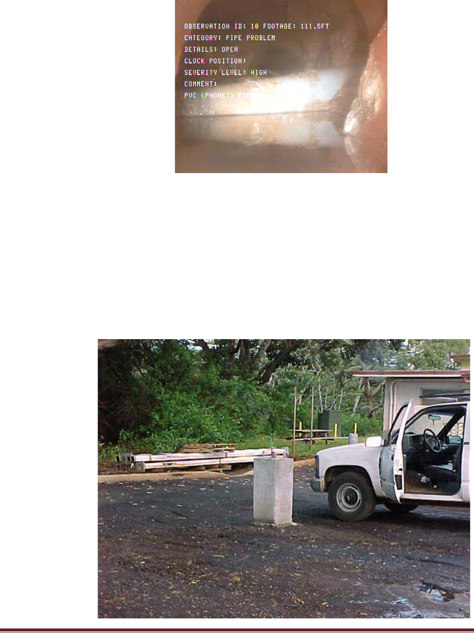
NAVFACMAR PWUC
15 November 2018
This PWUC supersedes: PWUC dated 14July2011; Revision 1 dated 02April2015 52
Figure 3-3
Figure 3-4 depicts a deep concrete mounting base for a parking lot
light standard that was constructed directly over a 6” clay sewer main
pipe. The background topographic features on the design site plan
showed the existing sewer manholes, but no connecting mains were
depicted. In multi-discipline project designs, such omissions can result
in field conflict and costly change orders. The sewer main pipe was
crushed, resulting in a major sewage backup.
Figure 3-4
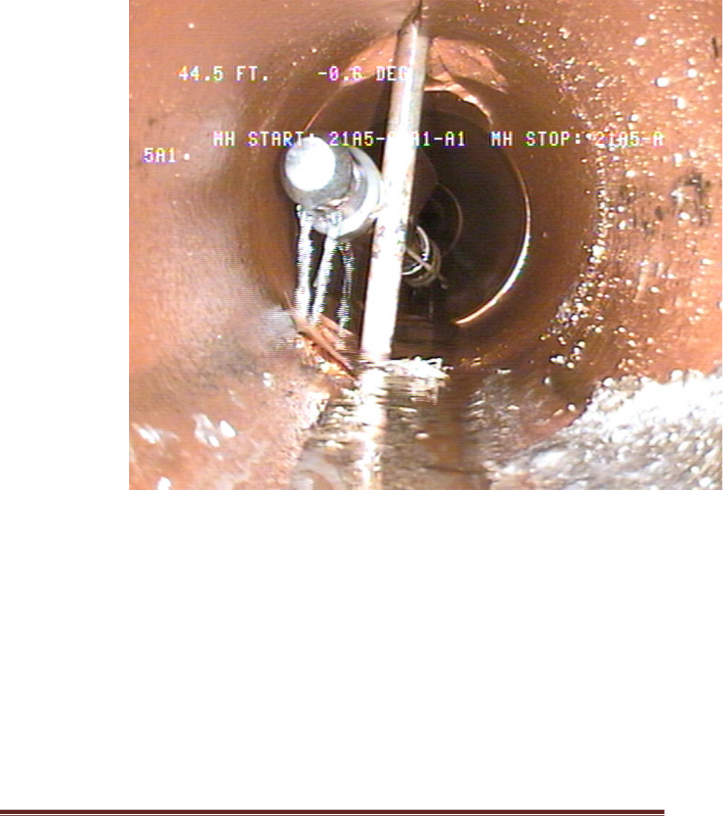
NAVFACMAR PWUC
15 November 2018
This PWUC supersedes: PWUC dated 14July2011; Revision 1 dated 02April2015 53
Figure 3-5 depicts a sewer flush-cleaning head that got stuck on a
grounding rod that was driven through a clay sewer main pipe.
Figure 3-5

NAVFACMAR PWUC
15 November 2018
This PWUC supersedes: PWUC dated 14July2011; Revision 1 dated 02April2015 54
b. Construction Notes (3.1.6).
1. The contractor shall be responsible for performing and maintaining
any incidental sewage bypass pumping or diversion work that will
be required to accomplish the construction work.
2. For any new concrete surface that will be exposed to sewage flow,
the contractor shall maintain sewage bypass/diversion operations
for the duration of the specified curing time for the concrete.
3. The contractor shall be responsible for providing and maintaining
temporary power as necessary to maintain normal lift station
operations.
Discussion for notes “1”, “2” and “3”: Some projects may require a
new manhole to be constructed over an existing live main that
requires the field channelization of the new concrete base or
demolition and reconstruction of the concrete base of an existing
manhole to accommodate a new flow channel. Raw sewage shall
not be permitted to contact the fresh concrete surface during its
specified curing period. Also, brief outages may be necessary when
working on primary or secondary power affecting an existing lift
station. In such instances, the contractor shall provide and maintain
bypass provisions or temporary generator power to maintain normal
lift station operations. In cases where portable generator provisions
may be needed in order to maintain normal lift station operations,
the following note might be more applicable.
4. The contractor shall be responsible for damage to any Government
utility system resulting from construction operations; any damage
shall be reported immediately to the Contracting Officer or
appropriate Government Representative. Any sewer repair
performed by the contractor shall be inspected by the
NAVFACMAR PWD Utilities Inspector prior to backfilling.
Discussion for note “4”: This general comment should be included
on all construction drawings, whether or not work is to be
performed on a utility system, especially when excavation is
involved or where vibratory stresses may affect underground utility
lines (such as pile driving operations or where site demolition may
involve the use of a heavy tracked vehicle like an excavator). Also,
projects that require the construction of wall footings, fence post
footings, sign footings, concrete base mounts for outdoor lighting
structures, guy anchors for poles and electrical grounding rods can
also damage underground utility lines. For underground mounting
structures that have the potential for exerting lateral soil pressures
on adjacent underground utility lines (wind loads on flag poles,
vehicle impacts to sign posts, etc.), a design evaluation should be

NAVFACMAR PWUC
15 November 2018
This PWUC supersedes: PWUC dated 14July2011; Revision 1 dated 02April2015 55
performed by a qualified structural or soils engineer.
5. The contractor will be responsible for regulatory fines or penalties
that may be imposed by environmental regulatory agencies (EPA
and/or State DOH) in the event of sewage overflow or spill resulting
from construction operations.
Discussion for note “5”: The Navy’s wastewater collection,
transmission and treatment systems are under the strict regulatory
guidance of the Federal Environmental Protection Agency (EPA)
Region IX and the State of Hawaii Department of Health (DOH).
6. The contractor shall reimburse the Government for any emergency
response effort that may be required by Government forces to
mitigate the adverse effects of any sewage overflow or spill
resulting from the contractor’s operations.
Discussion for note “6”: This note would typically be used together
with note “e” above. Contractors shall reimburse NAVFACMAR
BOSC for costs associated with such government emergency
response efforts, which may include material, equipment and labor
costs. For certain critical projects, the contractor should have an
account established with NAVFACMAR Comptroller prior to
commencing construction work.
7. Any sewer manhole to be abandoned shall have its cone section
removed and disposed of, pipe penetrations plugged with Class “C”
concrete and the remaining riser structure backfilled and
compacted to finish grade. (and/or)
8. Cleanouts on any abandoned service lateral shall be plugged and
terminated a minimum of 12 inches below finish grade.
9. Prior to abandonment, pipe shall be filled with flowable fill as noted.
Discussion for notes “7”, “8” and “9”: The intent of this requirement
is to minimize the potential for localized soil erosion into abandoned
void spaces that could eventually result in the development of
sinkholes. This also prevents unauthorized connections to
abandoned portions of the collection system. Under certain
situations, NAVFACMAR PWD UEM may require that abandoned
pipe be filled with flowable fill prior to abandonment.
10. The contractor shall contact the Supervisor of the NAVFACMAR
BOSC Line Section to make arrangements for the Government to
take custody of salvageable sewer manhole frames and covers.
Manhole frames and covers not accepted by the Government shall
be disposed of by the contractor.

NAVFACMAR PWUC
15 November 2018
This PWUC supersedes: PWUC dated 14July2011; Revision 1 dated 02April2015 56
Discussion for note “10”: The applicability of this note would be
determined on a case-by-case basis during the design phase
based on the quantity and type(s) of frames and covers. Standard
Type SA and SB frames and covers can be reused by the
NAVFACMAR BOSC Line Section; older types generally do not
have any reuse value.
11. When working on dockside or under pier ship wastewater collection
system piping, the contractor shall first mechanically secure and tag
out hose connections along the entire length of the common
pressure manifold prior to working on the system.
Discussion for note “11”: In the field, it may not be readily apparent
that dockside ship wastewater hose-connection risers are
interconnected through a common under pier pressure collection
manifold. Besides addressing the concern for possible sewage
discharges into harbor waters, the primary intent of this note is to
protect the contractor’s workers from accidents that could result
from unanticipated pressure discharges into the common pressure
manifold from an adjacent ship berthing area, particularly from
submarines (high pressure pneumatic blow downs). The designer
should clearly depict the extent of any common pressure manifold
in the construction drawings.
12. Potentially lethal levels of hydrogen sulfide (H2S) gas may develop
in the gravity sewer collection system.
Discussion for note “12”: For a worker who is not familiar with the
layout and operation of a localized portion of a sewer collection
system, intermittent upstream pressure main discharges into the
gravity collection system may not be readily apparent. During the
time the upstream pressure transmission system is inactive
(associated lift station not actively conveying flow), there is the
potential for hazardous hydrogen sulfide gases to develop in the
airspace of the inactive pressure main pipe. When the associated
lift station initiates flow transmission in certain areas, the hydrogen
sulfide gas that can form in the pressure main pipe can be
evacuated into the downstream gravity collection system which
could have an immediate adverse effect on the air quality in gravity
system manholes immediately downstream of the pressure main
discharge. The same kind of hazard can be encountered in gravity
manholes immediately downstream of anaerobic ship/submarine
collection and transfer (CHT) tank discharges. Under such
circumstances, continuous monitoring of the air quality in the
manhole space may not be sufficient to protect the life and safety of
worker inside the manhole unless the worker is fully equipped with
a self-contained breathing apparatus (SCBA). The designer should

NAVFACMAR PWUC
15 November 2018
This PWUC supersedes: PWUC dated 14July2011; Revision 1 dated 02April2015 57
ensure that applicable confined space entry requirements and
specifications are included in the construction contract.
13. The contractor shall ensure that loose material, tools and
equipment from construction operations are appropriately removed
from the sewer collection system. Any damage to downstream lift
station equipment resulting from negligence will be assessed to the
contractor.
Discussion for note “13”: Such items as grout mix buckets and
brushes (from manhole interior finishing), lengths of tracer wire,
cable strands, mop heads, etc. have been dislodged from pump
impellers. Also, backfill gravel and pavement base course material
have been removed from gravity collection mains.
14. Prior to securing potable water outages in mains or service
connections, the contractor shall first provide and maintain a
backup seal water provision to lubricate pump seals at the affected
sewer lift station shown on the plans. Coordinate access to the
affected lift station, at least 3 days in advance of the outage, with
the NAVFACMAR BOSC Lift Station Supervisor.
Discussion for note “14”: The sewage pump seals at most large
(multi-level) Navy sewage lift stations are lubricated with water from
the Navy potable water distribution system. Prolonged water
outages will result in damage to pump seals and could ultimately
result in pump failure. The designer should first identify any sewage
lift station that may be affected by the water outage (plan file
research, field investigation and/or consultation with cognizant
NAVFACMAR Potable Water personnel) and ascertain whether its
pumping units utilize potable water for pump seal lubrication
(contact the NAVFACMAR BOSC Lift Station Supervisor).
15. Adjust all manhole frames and covers to the new finish grade.
Discussion for note “15”: There have been roadway resurfacing
projects and pedestrian walkway projects that have effectively
buried sewer manholes. This note should also be used on projects
that involve the changing of finish grades in the vicinity of
manholes. It is generally assumed that the designer for such
projects will exercise due diligence in researching and identifying
any and all underground utility systems that may be affected. On
projects that involve manhole frame/cover adjustments, the
designer should also provide a detail for the adjustment.
16. Make advance arrangements (3 working days minimum), through
the Contracting Officer, with the Line Section Supervisor of

NAVFACMAR PWUC
15 November 2018
This PWUC supersedes: PWUC dated 14July2011; Revision 1 dated 02April2015 58
NAVFACMAR PWD Utilities for joint ROICC/NAVFACMAR PWD
Utilities inspection of any new wye saddle construction. (applicable
to new service connections to existing sewer mains)
Discussion for note “16”: The construction contract shall require
that a project account be established with the NAVFACMAR
Comptroller for these special Government inspections; the
cognizant ROICC construction contract administrator should
provide the NAVFACMAR PWD Utilities with the applicable job
order number for the inspection at the time of scheduling the
inspection. Such inspections will be required for all construction
projects where work is performed on the Navy’s sewer system,
even when such connections are an incidental part of a larger
project scope. Poor workmanship in the construction of wye saddle
connections has been a contributing factor in some line blockages;
for this reason, sanitary wye fittings are preferred where possible.
For new service connections to existing sewer manholes, the joint
ROICC/ NAVFACMAR PWD Utilities inspection can be performed
during the final acceptance inspection for the overall construction
project.
17. During periods of non-work and for the duration of contract work
within the secured perimeter of the lift station, the contractor is
responsible for securing access gates, doors and security. After
normal working hours, the contractor is responsible for properly
securing access gates, doors and security fencing.
Discussion for note “17”: In most instances, it might be appropriate
to use this construction note in conjunction with earlier note “e”.
During lunch breaks away from the lift station site, workers shall
lock the access gate(s) to the lift station to prevent unauthorized
entry. In some cases, the contractor may be permitted to
temporarily remove perimeter chain link fence fabric to facilitate
construction work at the lift station. In such instances, the
contractor shall permanently re-affix the chain link fabric using
appropriate hardware in order to prevent unauthorized access
whenever the work site is left unattended.
18. Upon completion of the sewer construction, make advance
arrangements (3 working days minimum), through the Contracting
Officer, with NAVFACMAR PWD UEM for final acceptance
inspection of the new sewer construction.
Discussion for note “18”: Field construction that is not covered by a
CCTV inspection submittal (refer to Section 2.13.5, Post-
Construction CCTV Inspection) will be addressed during the final
walk-through inspection.
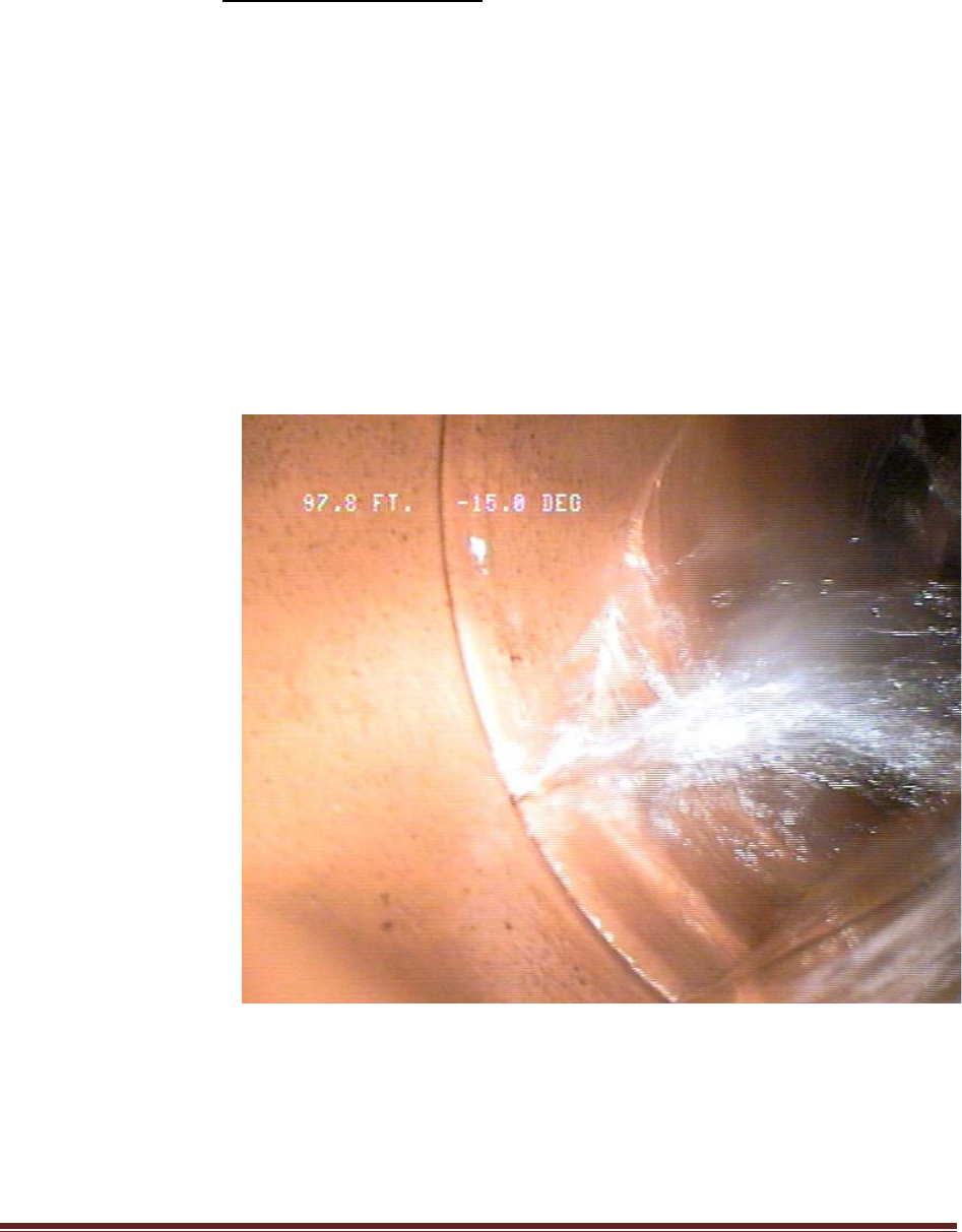
NAVFACMAR PWUC
15 November 2018
This PWUC supersedes: PWUC dated 14July2011; Revision 1 dated 02April2015 59
19. Construction dewatering into the Navy’s sewer collection system is
prohibited.
Discussion for note “19”: Environmental compliance requirement as
directed by the Navy’s Federal Facility Compliance Agreement with
EPA Region IX.
c. Pipe Bedding (3.2.9).
Figure 3-6 depicts a fracture originating at a clay pipe joint with
groundwater inflow. The 45-degree angle of the fracture relative to
horizontal and vertical sectional planes suggests shear stress at work
on the joint face. Providing graded granular trench bedding material
around the entire circumference of the pipe will minimize the
development of concentrated stresses at pipe joints.
Figure 3-6
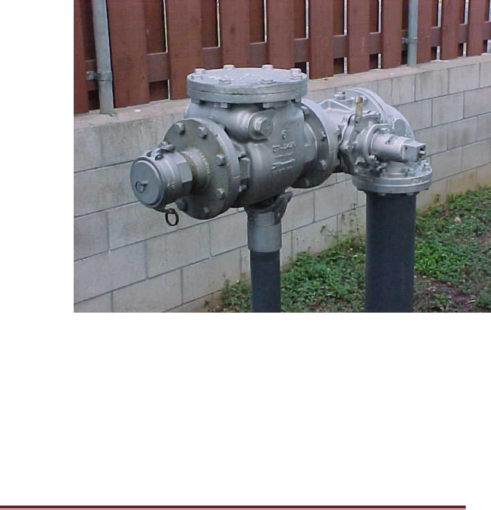
NAVFACMAR PWUC
15 November 2018
This PWUC supersedes: PWUC dated 14July2011; Revision 1 dated 02April2015 60
d. Emergency Pump Connection (3.3.21).
Figure 3-7 depicts a “riser” type hose connection assembly with a female
cam-lock hose receptor and male plug, check valve and plug valve.
Figure 3-7

NAVFACMAR PWUC
15 November 2018
This PWUC supersedes: PWUC dated 14July2011; Revision 1 dated 02April2015 61
3.5.3 Special Details.
Figure 3-8
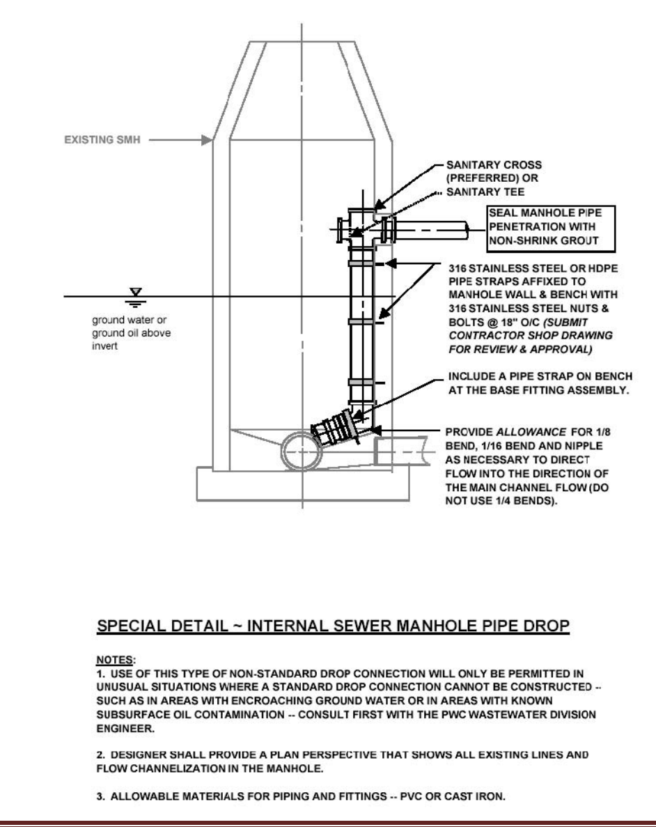
NAVFACMAR PWUC
15 November 2018
This PWUC supersedes: PWUC dated 14July2011; Revision 1 dated 02April2015 62
Figure 3-9

NAVFACMAR PWUC
15 November 2018
This PWUC supersedes: PWUC dated 14July2011; Revision 1 dated 02April2015 63
3.6 Special GWA Requirements for Tie-Ins.
Contractor shall comply with GWA Final Developer Guidebook 2010 for
tie-in connections to existing GWA sewers.

NAVFACMAR PWUC
15 November 2018
This PWUC supersedes: PWUC dated 14July2011; Revision 1 dated 02April2015 64
CHAPTER 4 - WATER
4.1 GENERAL INFORMATION.
This section covers general information for the water distribution system,
and water related facilities, including pump stations and reservoirs, as
applicable.
4.1.1 Subsurface Oil.
For all excavation work in the Naval Station, and Fleet Industrial Supply
areas, subterranean oil may be encountered. Check with the
NAVFACMAR EV coordinator for known or suspect contaminated soil
locations. Include appropriate construction and contract specifications to
address the handling and disposal of contaminated materials as
necessary.
4.1.2 Existing Underground Utility Lines.
Plans and specifications shall require toning for underground utilities.
Toning of the excavation area shall be performed prior to commencement
of any excavation work. In areas where nonmetallic pipe lines may be
present, ultrasonic detection methods or field-locating grade nodes
(manholes, valve boxes, cleanouts, etc.) may be used as appropriate.
Ground Penetrating Radar (GPR) systems shall be used prior to
excavation in all Shipyard areas. Research as-built construction drawings
and perform field investigations to ensure all known underground utility
lines are identified on the construction drawings prior to actual field
excavations. Perform soil borings sampling and testing when required.
Include a note and/or specification to indicate the cost of repairing any
damaged underground utility line shall be borne by the Contractor
regardless of whether or not the utility lines are depicted on the
construction drawings.
4.1.3 Outages.
The contractor shall request water outages via the NAVFACMAR BOSC
Service Support Center (telephone number 333-2011) via the Contracting
Officer’s representative, thirty (30) days prior to the desired date of the
outage. The contractor shall ensure that approval has been obtained for
the outage prior to performing work. All water outages shall be performed
by the NAVFACMAR BOSC, unless otherwise directed by the CME.

NAVFACMAR PWUC
15 November 2018
This PWUC supersedes: PWUC dated 14July2011; Revision 1 dated 02April2015 65
4.1.3.1 Outage Duration.
Coordinate the water outage duration with the NAVFACMAR BOSC.
Water outages affecting an individual facility should not exceed four (4)
hours. Provide temporary water service to affected facilities when water
outages exceed four (4) hours, unless an outage duration beyond four (4)
hours is approved by the facility or housing manager and the Guam Naval
Base Fire Chief.
4.1.4 Connections to the Water Distribution System.
The Contractor shall provide the NAVFACMAR BOSC fourteen (14) days’
notice prior to connecting to any waterline.
4.1.4.1 Wet Tapping Mains Twelve Inches (12”) and Smaller.
a. The contractor shall be responsible for the following:
1. Material, Labor and Equipment – Except as otherwise indicated, the
contractor shall provide all material, labor and equipment to
connect new exterior water lines to the existing NAVFACMAR PWD
water distribution systems by use of tapping sleeves and tapping
valves or corporation stops.
2. Timing – The contractor shall perform the disinfection work at the
connection just prior to installation of the tapping. The disinfection
work shall be performed in the presence of the CME, NAVFACMAR
PWD Utilities personnel, and NAVFACMAR EV personnel. The
disinfection work shall be performed by a licensed Level 2 Water
System Operator.
3. Coordination and Notification - The contractor shall coordinate work
with the NAVFACMAR BOSC. The Contractor shall provide
NAVFACMAR BOSC a minimum of 14 days advance notice prior to
the date of the tap. Point of contact on this matter is NAVFACMAR
BOSC Service Support Center, telephone number 333-2011.
4. Payment of Government Services - Work by NAVFACMAR PWD
UEM on NAVFACMAR projects shall be done on a cost
reimbursable basis. All contracts requiring tapping of existing
NAVFACMAR PW exterior water lines shall reflect this
reimbursement requirement (see section 4.1.6).
b. The Contractor will provide, install and operate the tapping machine.
The equipment necessary for the installation and operation of the
tapping machine as well as the necessary cutting blades will also be
provided by the Contractor. Disinfection of the tapping machine will be

NAVFACMAR PWUC
15 November 2018
This PWUC supersedes: PWUC dated 14July2011; Revision 1 dated 02April2015 66
done by the Contractor. All other work not specifically indicated as
being performed by the government shall be done by the contractor.
4.1.4.2 Tapping Sleeve and Valve Materials.
Tapping sleeves shall be either cast or ductile iron with mechanical joint
ends, unless otherwise approved by NAVFACMAR PWD UEM. All
tapping sleeves and tapping valves shall be a matched set and conform to
AWWA specifications. (The project designer shall indicate the appropriate
AWWA specifications.) The tapping valve shall be flanged by mechanical
joint for connecting to the tapping machine.
4.1.4.3 Other Connections Including Wet Tapping Mains for Larger than 12”
Lines.
The contractor shall perform all connection work. The connection work
shall be performed in the presence of the CME. The contractor shall
provide the NAVFACMAR BOSC a minimum of fourteen (14) days
advanced notice for the above purpose. All work and services provided by
the NAVFACMAR PWD UEM are on a cost reimbursable basis.
4.1.5 Contractor Submittals.
Contractor submittals shall be forwarded to NAVFACMAR PWD UEM, via
the Contracting Officer, for review and approval as applicable. See
Chapter 1.
4.2 WATERLINES.
This section covers requirements for waterline installations and repairs, as
applicable.
4.2.1 General Location.
Structures shall not be located over existing waterlines, except that a
building may be extended over laterals if the lateral serves only that
building. Waterlines shall not be designed within roadway areas unless the
waterline’s crossing is required for tie-in and/or completing the design for
the service area.
4.2.2 Clearances.
4.2.2.1 Clearances from Structures and Other Utilities (Excluding Sewer Lines).
Adequate clearance or a minimum of 5 feet between the edge of a
building (wall and roof line) and a waterline should be provided to enable
repair of the lines by use of heavy equipment. Three (3) feet horizontal

NAVFACMAR PWUC
15 November 2018
This PWUC supersedes: PWUC dated 14July2011; Revision 1 dated 02April2015 67
clearance shall be provided between waterlines and other utilities (except
sewer lines). Vertical clearances shall be a minimum of six (6) inches.
Whenever concrete jackets are involved, the clearances shall be the total
clear distance between the concrete jacket and the utility line.
4.2.2.2 Horizontal Clearances from Sewer Lines.
A horizontal clearance of 10 feet shall be provided between water lines
and sewer lines or manholes. If this clearance cannot be provided
because of site conditions, the new waterline may be laid closer to 6 feet
clearance between the lines provided the following requirements are met:
a. The bottom (invert) of the water piping shall be at least 12 inches
above the top (crown) of the sewer piping. Where this vertical
separation cannot be obtained, the sewer piping shall be constructed
of AWWA-approved water pipe and pressure tested in place without
leakage prior to backfilling.
b. The sewer manhole shall be of watertight construction and tested in
place.
Note: Where water mains and sewers follow the same roadway, they will
be installed on opposite sides of the roadway, as approved by
NAVFACMAR PWD UEM.
4.2.2.3 Vertical Clearances from Sewer Lines.
Water piping shall cross above sewer piping and shall be laid to provide a
separation of at least 24 inches between the bottom of the water piping
and the top of the sewer piping. If this provision cannot be obtained
because of site conditions, the following requirements shall be met.
a. If the new waterline crosses above the sewer line, provide a concrete
jacket for the sewer line a horizontal distance of three (3) feet on both
sides of the crossing.
b. If the new waterline crosses below the sewer line, provide a concrete
jacket for the sewer line a horizontal distance of five (5) feet on both
sides of the crossing. Provide adequate structural support for the
sewer piping to prevent excessive deflection of the joints and settling
on and breaking of the water piping. The length of the water piping at
the crossing shall be a minimum of twenty (20) feet, and shall be
centered at the point of the crossing so that the joints shall be
equidistant and as far as possible from the sewer piping.
c. No water piping shall pass through or come in contact with any part of
a sewer manhole.

NAVFACMAR PWUC
15 November 2018
This PWUC supersedes: PWUC dated 14July2011; Revision 1 dated 02April2015 68
4.2.3 Cover.
The minimum cover for transmission mains shall be three (3) feet. The
minimum cover for water service laterals 2-1/2 inches and smaller shall be
2.5 feet in paved areas, and 2 feet in non-paved areas. The maximum
cover over waterlines shall be eight (8) feet.
4.2.4 Pipe Jackets.
Use reinforced concrete pipe jackets where minimum pipe cover is not
available, and where minimum vertical clearances between sewer and
water lines cannot be obtained. When concrete jackets are provided, they
shall be provided with reinforcement. All concrete jackets shall start and
end at a pipe joint and the jacket shall be placed in a manner that will
allow the aforementioned joints to deflect.
4.2.5 Warning Tape and Tracer Wire.
Require the installation of buried warning and identification tape for all
waterlines. Require a tracer wire be provided for all non-metallic pipes. At
water valve buffalo boxes, the tracer wire shall be cut and both ends shall
extend to within 6” from the top of the boxes. At water valve boxes the
tracer wire shall extend into the box.
4.2.6 Deflections.
Maximum deflection for pipe joints shall be limited to 80% of the deflection
recommended by the manufacturer.
4.2.7 Pipe and Fittings.
Water distribution mains indicated as 100 through 400 mm (4 through 16
inches) diameter pipe sizes shall be polyvinyl chloride (PVC) plastic pipe,
and as an option ductile-iron may be considered. Provide high density
polyethylene (HDPE) pipe for 400 mm (16 inch) diameter or larger pipe
sizes. Verify with NAVFACMAR PWD utilities for the appropriate use of
HDPE as water distribution mains. The designer shall have the option of
selecting High Density Polyethylene (HDPE) Plastic Piping, but shall verify
if there are any adverse effects with long term exposure to chlorinated
water on HDPE pipe. Pipe, tubing, and heat-fusion fittings for High Density
Polyethylene pipe shall conform to AWWA C906, ASTM D 3035 and
ASTM D 3261. The designer shall have the option of selecting Fusible
Polyvinyl Chloride (PVC) Pipe, conforming to AWWA C-900/C-905, but
shall verify with the Contracting Officer prior to designing.

NAVFACMAR PWUC
15 November 2018
This PWUC supersedes: PWUC dated 14July2011; Revision 1 dated 02April2015 69
4.2.7.1 Ductile Iron.
Ductile iron pipe and fittings shall conform to AWWA C151. Four (4) inch
diameter mains shall be thickness class 53 (minimum). Mains six (6)
inches in diameter and larger shall be thickness class 52 (minimum).
Loading and pressure considerations shall determine if a higher class is
required. Flanged pipe shall conform to AWWA C115, and flanged fittings
shall conform to AWWA C110 or AWWA C153. Pipe and fittings shall
have cement-mortar lining conforming to AWWA C104, standard
thickness. Provide polyethylene encasement except when cathodic
protection is provided.
4.2.7.2 PVC
PVC pipe shall conform to AWWA C900, and shall be a minimum
pressure class 235 (DR 18). Pipes fourteen (14) inches through thirty-six
(36) inches in diameter shall conform to AWWA C905. Fittings for PVC
pipe shall be ductile iron.
4.2.7.3 Minimum Size
Minimum diameter for distribution mains and fire branches is six (6)
inches.
4.2.8 Disinfection
All new or repaired potable water lines, fire protection main lines
connected to the potable water system and that are upstream of the
backflow prevention device, irrigation lines that are upstream of the
backflow prevention devices and affected portions of existing potable
water lines shall be flushed and disinfected. All work shall be done at the
contractor’s expense. The disinfection work shall be performed by a
licensed Level 2 Water System Operator.
4.2.8.1 Disinfection of New Waterlines.
Include following notes in the project specifications or in notes on the
drawings.
a. Disinfection of water lines, including flushing and bacteriological
testing, shall be in accordance with AWWA C651 (latest edition) except
as otherwise indicated below.
b. All connections to existing water lines shall be done in a “dry” trench.
When the existing water line has to be dewatered, the contractor shall
accomplish the dewatering of the line in a manner such that the
connection to the existing system can be done in a “dry” trench. The

NAVFACMAR PWUC
15 November 2018
This PWUC supersedes: PWUC dated 14July2011; Revision 1 dated 02April2015 70
contractor shall submit a dewatering plan for approval.
c. For new pipe sections, chlorine shall be applied by the continuous feed
method unless prior approval has been obtained to use a different
method. Calcium hypochlorite granules shall be placed in new pipe
sections (except solvent-welded plastic and screwed joint steel pipe)
during construction as specified in AWWA C651.
d. When the line is chlorinated, water entering the line shall receive a
dose of chlorine fed at a constant rate such that the water will have not
less than 50 mg/L of free chlorine.
e. At the end of a 24-hour period the treated water shall have a residual
of not less than 25 mg/L free chlorine.
f. During the chlorination period all valves and hydrants in the section
being treated shall be operated a sufficient number of times to
thoroughly disinfect the appurtenances.
g. All meters shall be disinfected with the water line except when
otherwise approved by the Contracting Officer.
h. The contractor shall notify the CME three (3) working days prior to
connecting to an existing Navy water line or disinfecting a new or
existing line.
4.2.8.2 Disinfection for Repair and Connections to Existing Lines. Include
following notes in the project specifications or in notes on the drawings.
a. Disinfection procedures for repairs/ connection work shall be as
indicated in AWWA C651 under the paragraph titled “Disinfection
Procedures When Cutting Into Or Repairing Existing Mains” except
that a 5% hypochlorite solution shall be used.
b. All tapping sleeves shall be disinfected as follows:
1. Thoroughly clean the exterior surface of the main to be tapped, the
surfaces of the tapping sleeve and the surfaces of the tapping
equipment that will come into contact with the water.
2. Thoroughly swab the main, the tapping sleeve and the tapping
equipment with a 5% sodium hypochlorite solution.
3. Any surfaces that become contaminated after being disinfected
shall be re-cleaned and re-swabbed as indicated above.
c. After final flushing and prior to placing new lines in service,

NAVFACMAR PWUC
15 November 2018
This PWUC supersedes: PWUC dated 14July2011; Revision 1 dated 02April2015 71
bacteriological tests shall be performed as indicated in AWWA C651
and as follows:
1. Standard Conditions: At least one sample shall be collected from
the end of each new main and one from the end of each new
branch line. In addition, one additional sample shall be collected for
each 4,000 feet of main or branch line. For example: for a 9,000
feet main, 3 samples are required i.e. 2 additional samples and one
sample at the end. The location of the additional samples shall be
determined by the contractor and approved by the Contracting
Officer.
2. Special Conditions: If during construction, trench water has entered
the line or if in the opinion of the Contracting Officer excessive
quantities of dirt or debris have entered the line, samples shall be
taken at intervals of approximately 200 feet and shall be identified
by location.
d. Disinfection of mains and branch lines shall be repeated until samples
show the absence of coli form organisms.
e. Final bacteriological test results, that show the absence of coli form
organisms, shall be provided to the CME at the final inspection of the
project or prior to placing the line in service whichever occurs first. The
location where the bacteriological samples were taken shall be
identified.
f. The contractor shall notify the CME three (3) working days prior to
connecting to an existing Navy water line or disinfecting a new or
existing line.
4.2.9 Cathodic Protection.
Unless specified otherwise, all runs of metallic pipes of 1000 feet or longer
shall be provided with cathodic protection if the field conditions indicate
that such protection is required. If cathodic protection is provided,
polyethylene encasement shall not be provided. Check if the existing
waterline that the project will be connected to has a cathodic protection
system or provisions for such a system, and for existing impressed current
systems in the vicinity of any new waterline. Design the connection point
and new waterlines accordingly.
4.2.10 Coating for Waterlines under Piers.
New waterlines under piers shall have an epoxy-polyamide coating
system conforming to MIL-P-24441. In addition, the word “water” shall be

NAVFACMAR PWUC
15 November 2018
This PWUC supersedes: PWUC dated 14July2011; Revision 1 dated 02April2015 72
stenciled onto the pipe.
4.3 WATER VALVES.
This section covers requirements for water valve installations.
4.3.1 Direction to Open.
The standard direction of opening shall be left (counterclockwise) as
viewed from the top.
4.3.2 Valve Boxes.
Provide a valve box (not buffalo box) for all butterfly valves, for all gate
valves 16” and larger and for those gate valves which have more than 5’
of cover measured from the top of the valve stem to the finish grade.
When such a box is provided, the box shall have a 6” CI frame and cover
over the valve operator to allow operation of the valve from ground level
and the valve shall be NRS type. This latter requirement may not apply to
large valves in meter boxes. These will be treated individually.
4.3.2.1 Painting of Valve Box Covers.
All valve covers shall be painted yellow except that covers for valves
controlling fire hydrants shall be painted white, and covers for valves that
are normally closed shall be painted yellow with a painted red diamond
centered on the top of the cover. Valve box frames shall be painted with
the same color as their cover except for valves that are normally closed,
which shall be painted only red. Mark all covers.
4.3.2.2 Identification Tags.
Provide identification tags for valves, and affix to the underside of all new
valve box or manhole covers. See Figure 4-1.
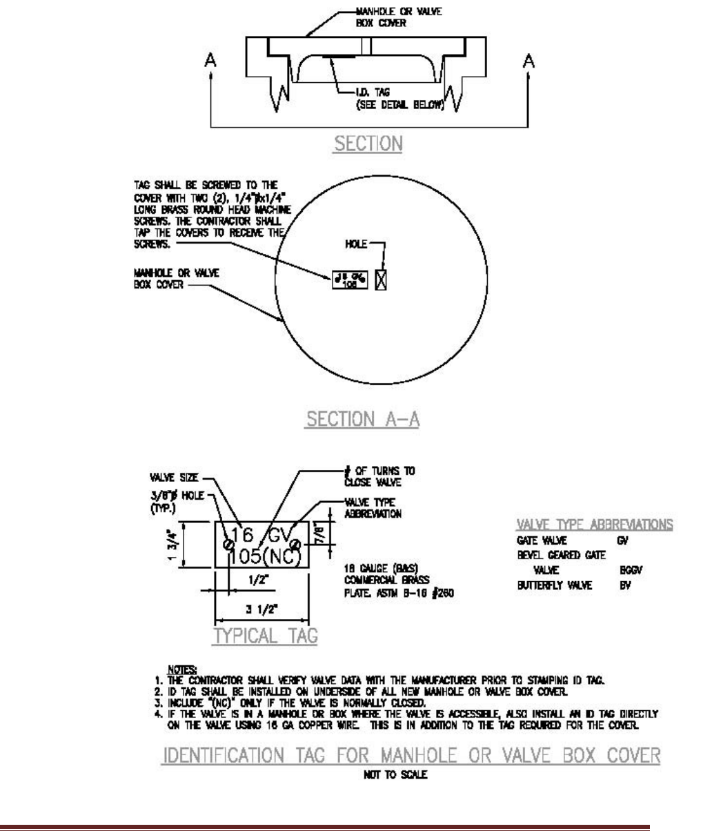
NAVFACMAR PWUC
15 November 2018
This PWUC supersedes: PWUC dated 14July2011; Revision 1 dated 02April2015 73
Figure 4-1

NAVFACMAR PWUC
15 November 2018
This PWUC supersedes: PWUC dated 14July2011; Revision 1 dated 02April2015 74
4.3.3 Corporation Stops for Valves.
All valves 16” and larger shall be provided with a corporation stop on each
side of the valve.
4.3.4 By-Pass and Gearing.
Gate valves 16” and larger shall be provided with a by-pass and gearing.
4.3.5 Butterfly Valves.
Except where tapping valves are required for all valves 12” and larger
shall be butterfly valves conforming to AWWA C504, CLASS 150B. Valves
shall be short body type with a cast iron body. Provide bypass.
4.3.6 Resilient-Seated Gate Valves.
Except for high pressure water systems and special cases, require that
gate valves 4” to 12” be resilient-seated type, conforming to AWWA C509.
The valves shall also be suitable for throttling and be coated on the interior
and exterior with an epoxy coating. The interior epoxy coating shall be
suitable for potable water use. All buried valves shall be NRS type.
Valves in boxes (non-buffalo type boxes) shall be labeled on the drawings
as to type of operating mechanism i.e. OS & Y or NRS. (Note: these
valves have a working pressure of 200 psi, therefore any references to
150 class valves should be deleted).
4.3.7 Flange Coupling Adapters.
Whenever possible, valves in boxes (non-buffalo type boxes) shall be
provided with flange coupling adapters.
4.3.8 Anchor Blocks.
Reinforced concrete anchor blocks with 316 stainless steel straps and
anchor bolts shall be provided for all valves connected to PVC pipes.
4.3.9 Service Saddles.
When required, service saddles shall be bronze with a 316 stainless steel
double strap.
4.3.10 Backflow Preventers.
An approved backflow prevention device on a service lateral shall be
required if there is a potential for contamination to the NAVFACMAR PW
water supply and distribution system. NAVFACMAR BOSC will determine
the degree of hazard for any new facility.

NAVFACMAR PWUC
15 November 2018
This PWUC supersedes: PWUC dated 14July2011; Revision 1 dated 02April2015 75
4.3.10.1 Testing and Inspection.
Require that all installed backflow preventers be tested and inspected by
the contractor using a certified tester at the time of the tap. Backflow
preventer testing and inspection by the NAVFACMAR BOSC shall be
done on a cost reimbursable basis. Also require that all discrepancies
found shall be repaired at the contractor’s expense.
4.3.11 Fire Hydrants.
Only wet barrel type fire hydrants shall be specified. All fire hydrants shall
be painted yellow, color 13655 of Federal Standard No. 595a.
4.4 WATER METERS.
This section covers requirements for water meter installations.
4.4.1 Meter Requirements.
For billing purposes, all potable water shall be metered for revenue
purposes by either a master meter for the area or by an individual meter
for the facility or site except as otherwise indicated. When a new service
is within an area which already has a master meter, a new meter is always
required if the activity who requires the service is different from the one
who is billed by use of the master meter. Meters are owned and
maintained as a functional part of the water distribution system, as well as
the enclosures, switches,
For each facility/building consuming water, provide water consumption
meters. Meters are owned and maintained as a functional part of the water
distribution system, as well as the enclosures, switches, cabling,
encoders, RTUs, and other accessories that are critical to meter
operation.
The NAVFAC Marianas Advanced Metering (AMI) system is the required
system for utility revenue meters to connect to. The AMI system uses
Modbus/TCP over Cat6 Ethernet and single mode fiber to network all
meters back to centralized servers. New utility revenue meters are
required to be AMI meters, and shall be compatible, configured, and
integrated with the AMI system in conformance to the AMI system
architecture. All projects that will provide a new AMI meter shall include
the following as part of planning, design, and construction:
a. Installation of new or upgraded OSP fiber optic cable infrastructure
from the nearest NCTS wire center to the facility or structure that is
being metered, as needed, to ensure at least two pairs of single mode
fiber are available for use.

NAVFACMAR PWUC
15 November 2018
This PWUC supersedes: PWUC dated 14July2011; Revision 1 dated 02April2015 76
b. Installation of new or upgraded fiber optic cable termination panel,
network switch, enclosure, intrusion detection relay and lock, and
mounting pedestal, at the facility or structure that is being metered, as
needed, to ensure conformance to the AMI system architecture.
c. Installation of new or upgraded meter vault, service pipe, meter
bypass, valves, network cabling and drops, and electrical circuit (must
be homerun to a point that is upstream of any electrical meter), as
needed, to ensure conformance to the AMI system architecture.
d. Installation and commissioning of AMI meter, accessories, and all
other AMI equipment, to also include submission of a change request
form, cybersecurity commissioning as outlined in Section 5, delivery of
AMI system inventory and network diagram documentation updates,
and meter changeover documentation required by the NAVFAC
Marianas UEM billing group.
Provide a test/calibration valve for meter calibration to be checked without
needing to remove the meter. Meters shall be equipped with absolute
encoders and RTUs that are capable of providing consumption and peak
flow data via Modbus/TCP. Configure meter equipment with the nearest
appropriate AMI electric meter so that the electric meter automatically
queries and records consumption and peak flow data via the network.
Meter enclosures (and enclosures for associated equipment) shall be
located on the facility exterior wherever possible, in a location that will
ensure that utility personnel are able to freely access utility meters and
their respective enclosures. If a suitable wall is not available for mounting
AMI equipment, a reinforced concrete utility pedestal shall be provided to
mount all necessary AMI equipment. Provide reinforced concrete bollards
to prevent vehicle damage to AMI equipment if it is located such that it is
susceptible to damage caused by vehicle traffic, but do not place bollards
in such a way that access to the enclosures and equipment is limited. All
enclosures shall be capable of being secured via padlock, and shall be
rated NEMA 4X stainless steel grade 316 or better. Equip enclosures with
molybdenum alloy stainless steel padlocks, common keyed to match
existing. Provide surge protection devices and grounding as needed to
protect AMI devices, accessories, and communications pathways. Provide
a door sensor on the interior of each enclosure, to be wired as a digital
input for intrusion detection purposes.
Coordinate all meter installations with the BOSC. The installer and the
BOSC shall ensure that meter changeover information is properly
documented at the time of any meters being changed out, using a form to
be provided by NAVFAC Marianas UEM. Facility owner/activity must be
identified properly on the form to ensure recording for billing purposes.

NAVFACMAR PWUC
15 November 2018
This PWUC supersedes: PWUC dated 14July2011; Revision 1 dated 02April2015 77
Provide complete manufacturer documentation including installation,
maintenance, testing, and user manuals. Manufacturer documentation
shall also be provided for all other provided devices, accessories, and
software.
Requirements for network devices and pathways are given in Section 5.
4.4.2 Metering Exceptions.
Water which will be used only for fire sprinkler systems within buildings
normally need not be metered.
4.4.3 Metering of Lawn Sprinkler Systems.
For water conservation purposes, all new or modified lawn sprinkler
systems and other types of irrigation systems served by a 2-inch diameter
or larger line shall be provided with its own meter. This meter is required
even if the flow is already measured by another meter.
4.4.4 Meters 3 Inches and Larger.
Meters 3” and larger shall have a bypass if such an appurtenance is
necessary to maintain service when the meter is being calibrated or
repaired. Include provisions for testing the meter’s accuracy in the field.
Provide adequate straight pipe sections before and after the meter as
recommended by the manufacturer.
4.5 MECHANICAL AND ELECTRICAL EQUIPMENT.
This section covers requirements for mechanical and electrical equipment
installations for water distribution.
4.5.1 Equipment.
In the design of a system, the designer should provide, on the drawings, a
narrative on the sequence of operation of the equipment including
electrical interlocks, alarms, timers, etc. The rationale behind the operation
should also be provided.
4.5.2 Operation and Maintenance (O & M) Manuals.
a. For a system, require the contractor to provide a manual that is tailored
to the system. The contractor must, in essence, extract the specific
information from the design drawings and equipment operating
manuals that he furnishes and describe in detail the sequence of
operation and the relationship between each piece of equipment.

NAVFACMAR PWUC
15 November 2018
This PWUC supersedes: PWUC dated 14July2011; Revision 1 dated 02April2015 78
b. Provide four (4) sets of bound copies and one digital copy of O & M
manuals to NAVFACMAR BOSC Water Manager (phone: 339-6109)
via the Construction Management Engineer.
4.5.3 Posting of Instructions.
For new equipment such as generators, process equipment, treatment
equipment, pumps, etc. require the posting of O & M instructions under
glass. State explicitly what information is to be posted for each piece of
equipment (some of the information which shall be posted is indicated
below) and the type of material to be used to mount the instructions. The
location where the instructions are to be posted is to be approved by the
Contracting Officer. Some types of posted information include:
a. Start-up sequence, normal running and shutdown sequences, along
with maintenance checks and lubrication requirements etc.
b. Information extracted from the design drawings and equipment
manuals. Include a system schematic diagram and post it at the newly
installed facility or equipment.
4.5.4 Labeling and Tagging of Electrical Wiring.
For all electrical work related to water process equipment, require that the
contractor label and tag all electrical connections in control boxes and
motor control panels. Require also that the wiring be neatly bundled and
that an “as-built” point-to-point wiring diagram be provided (in an
appropriate size) and mounted inside each electrical circuit. The diagram
shall also be included in the O & M manuals submitted with the
equipment.
4.5.5 Training.
If training is required for the operation and/or maintenance of new
equipment, indicate the exact training requirements by mentioning topics
or equipment for which training is to be provided, qualifications of the
instructors, and duration of training. Require that the contractor submit a
lesson plan for approval by the Contracting Officer. No training will be
scheduled until seven days after receipt of approvable O&M manuals.
4.5.6 Special Tool Requirements.
For any type of equipment, if special tools are required for operating,
maintaining or calibrating the equipment (including instruments and
meters) then the specifications are to require that these items be furnished
as part of the contract.

NAVFACMAR PWUC
15 November 2018
This PWUC supersedes: PWUC dated 14July2011; Revision 1 dated 02April2015 79
4.5.7 Spare Parts.
All spare parts recommended by the manufacturer should be provided
with the equipment. In addition, for recording equipment, a one year
supply of charts and ink shall be provided. Contractor Furnished Fuel,
Lubrication, Etc. If fuel, lubrication, etc. are required for startup and/or
testing of any equipment, the materials are to be provided by the
contractor and not by the Government.
4.5.8 SCADA
4.5.8.1 When modifying or adding new SCADA components, the components
shall be technically and operationally compatible with the existing Navy
Potable Water SCADA system. The installer shall integrate all modified or
added components with the existing SCADA system such that the
following criteria are satisfied:
a. All components shall have permanent communications paths to the
SCADA system server at Fena Water Treatment Plant (FWTP) control
room.
b. Monitoring and control of chemical feeds shall include, but not limited
to:
1. Coagulant (granular/liquid) chemical feed
2. Hypochlorite chemical feed
3. Fluoride chemical feed
4. Sodium hydroxide feed
5. Phosphate feed
6. Chloride level (at source)
7. Hypochlorite generation
8. Chlorine level/leak alarms
9. Chlorine injection monitoring
10. Chlorine Residual
c. Basic monitoring and controls shall include, but not limited to:
1. Pressure
2. Motor/pump control and status (runtime, temperature, speed,
notifications of failures or malfunctions, etc.)
3. Flow rate
4. Surface pressure (both sides of regulator) - pressure near the
wellhead and the discharge/distribution side
5. Groundwater level
6. Intrusion detection system alarm
7. Flush valve sensor
8. Filter flow/level control

NAVFACMAR PWUC
15 November 2018
This PWUC supersedes: PWUC dated 14July2011; Revision 1 dated 02April2015 80
4.6 MISCELLANEOUS APPURTENANTS.
This section covers other accessories installations for water distribution.
4.6.1 Valving.
Section valves are to be provided at all connections to the main. This
includes pump discharge, distribution connections, fire hydrants, blow offs,
air valves, and reservoir connection.
4.6.2 Air-vacuum Valves.
Combination air release and vacuum valves are to be installed at peaks,
where the pipe slope changes from positive to negative, and long
relatively straight stretches at ¼- to ½- mile intervals.
4.6.3 Blow-offs.
Blow-offs, with a drain to a disposal area, should be installed near low
points and other suitable locations to facilitate draining the conduit and
disposal of the water. Blow-offs will be designed with an air-gap to prevent
contaminated water from backing up into the main.
4.7 STORAGE.
This section provides criteria for water storage requirements.
4.7.1 Flow Requirements.
Storage should meet peak flow requirements, equalize system pressures,
and provide emergency water supply. The water supply system must
provide flows of water sufficient in quantity to meet all points of demand in
the distribution system and to satisfy maximum anticipated water
demands.
4.7.1.1 Minimum Pressures.
Water distribution system, including pumping facilities and storage tanks
and reservoirs, should be designed so that the water pressures of at least
40 psi at ground level will be maintained at all points in the system,
including the highest ground elevations in the service area. Minimum
pressures of 30 psi, under peak domestic flow conditions, can be tolerated
in small areas as long as all peak flow requirements can be satisfied.
During firefighting flows, water pressures should not fall below 20 psi at
the hydrants.

NAVFACMAR PWUC
15 November 2018
This PWUC supersedes: PWUC dated 14July2011; Revision 1 dated 02April2015 81
4.7.1.2 Maximum Pressures.
Maximum water pressures in distribution mains and service lines should
not normally exceed 75 psi at ground elevation. Static pressures up to 100
psi can be tolerated in distribution systems in small, low-lying areas.
Higher pressures require pressure reducing valves on feeder mains or
individual service lines to restrict maximum service pressures to 75 psi.
4.7.2 Water Storage Facilities.
Wherever feasible, design storage to provide flow through circulation, with
compartments.
Reinforced concrete or Pre-stressed concrete is the desired construction
of ground reservoirs and tanks because it produces structures with long
service lives, meets seismic requirements and which require little
maintenance. Concrete water tanks must be provided in accordance with
AWWA Standard D110 Wire- and Strand- Wound, Circular, Pre-stressed
Concrete Tanks, Type 1. Due to high maintenance, elevated steel storage
tank is no longer desired.
All treated water tanks and reservoirs must be covered to prevent
contamination by dust, birds, leaves, and insects. These covers will be
watertight at all locations except vent openings. Special attention should
be directed toward making all doors and manholes watertight. Vent
openings must be properly sized and protected to prevent the entry of
birds and insects; and vent screens should be kept free of debris so that
the air can enter and leave the storage area. All overflows or other drain
lines must be designed so as to eliminate the possibility of flood waters or
other contamination coming in contact with the treated water. Maintain
sufficient flow through the tank or reservoir so that stored water does not
become stagnant.
4.7.2.1 Piping Arrangement.
For large tanks, place inlet and outlet pipes at opposite ends or sides, to
provide circulation with the outlet pipe near the bottom. Otherwise, provide
baffles in the tank. Provide overflow and drain pipes discharging to storm
drains, but provide air gap to prevent contamination. Place valves on all
pipes except overflow pipes. Install all valves so that they will stand out of
groundwater or runoff, to prevent possible contamination, and to be easily
accessible to operating personnel.
4.7.2.2 Appurtenances.
Include outside tank ladder, roof hatch with lock, screened vent, water

NAVFACMAR PWUC
15 November 2018
This PWUC supersedes: PWUC dated 14July2011; Revision 1 dated 02April2015 82
level indicator (and alarm), sampling access points, and altitude or float
valves.
a. Provide altitude valve or float valve to fill, maintain water levels at, and
prevent overflows at tanks or reservoirs. Altitude valves will be installed
in concrete pits having provision for draining either by gravity or
pumping. Drains will not be connected to sanitary sewers.
b. To keep out insects and rodents, provide 20-mesh bronze insect
screens over all vent openings. The vents should be rain proofed by
using goose necks.
4.7.2.3 Disinfection.
Potable water storage facilities, associated piping, and ancillary equipment
must be disinfected before use. Disinfection will be accomplished following
procedures and requirements of AWWA C652. In no event will any of the
above equipment or facilities be placed in service prior to verification by
bacteriological tests, that disinfection has been accomplished.
4.7.2.4 Corrosion Control.
To prevent corrosion, all steel water structures shall have a protective
coating system, which prevents the current from flowing between the
metal and electrolyte, and an impressed-current cathodic protection
system.
4.7.2.5 Coatings.
Coatings used on interior surfaces of a tank, including that of a risers and
all other surfaces in contact with the water, must not add taste, odor,
toxicity, or impurities to the water; must readily adhere to the tank’s
surface while continuously submerged; must have a low rate of
permeability; and must meet the minimum requirements of NSF Standard
61.
4.7.2.6 To divert the surface runoff, grade and drain around ground storage tanks
or reservoirs.
Ground storage tanks and reservoirs should have watertight joints to avoid
contamination from subsurface sources.
Vaults and valve chambers should be watertight or self-draining.

NAVFACMAR PWUC
15 November 2018
This PWUC supersedes: PWUC dated 14July2011; Revision 1 dated 02April2015 83
4.8 PUMP STATIONS.
This section provides requirements for booster pump station construction
for water distribution.
4.8.1 Suction Piping Valves.
A gate valve will be installed in the suction piping so that the pump can be
isolated from the line
4.8.2 Discharge Piping Valves.
A check valve and a gate or butterfly valve will be installed in the
discharge piping with the check valve between the pump and the gate or
butterfly valve. Pressure relief valves, commonly diaphragm activated
globe or angle type, will be installed in discharge piping system for flow
control and/or pressure regulation, and to protect pump equipment and
piping system from excessive surge pressures.
4.8.3 Air Release and Vacuum Relief valves
Air release and vacuum relief valves will be used on discharge piping for
vertical turbine pumps.
4.8.4 Metering
Pump Station shall be provided with a water & power meter.
4.8.5 Reliability.
Pump Station reliability will be considered. The number of pumps will
depend upon present and future needs. Whenever a single pump is
sufficient, two equal size pumps, each able to handle the peak demand,
must be provided and set-up to alternate. Whenever two or more pumps
are cost effective to meet the peak demand, additional pump capacity or
pumps must be installed so that the peak demand can be met with the
largest pump out of service. All pumps should alternate. VFD motors
should be considered in all designs.
4.8.6 Backup (Emergency) Power Supply.
Design fuel storage to provide at least forty-eight (48) hours of continuous
run-time operation.

NAVFACMAR PWUC
15 November 2018
This PWUC supersedes: PWUC dated 14July2011; Revision 1 dated 02April2015 84
4.9 WELLS.
This section provides requirements for potable water well installation.
4.9.1 Drilling, Testing, Sampling, Development and Construction.
Contractor shall comply with the Guam Water Resource Development and
Operating Regulations (WRDOR) provisions, as amended and used by
Guam EPA.
4.9.2 EPA Compliance Well Monitoring.
Contractor shall provide the following additional equipment and features
for continuous compliance monitoring, to ensure minimum virus
removal/treatment requirement is met.
a. Two (2) continuous monitoring chlorine analyzers (one where chlorine
is added and another prior to the first customer)
b. pH meter
c. Temperature meter
d. Data recorder
e. Automatic switchover on chlorine tanks
f. Link shutoff of chlorine treatment system with shutoff of well or install
back-up power supply (generator) at each well (that automatically
switch on when power goes out).
g. Design well to provide chlorine contact time meeting the minimum virus
removal treatment at the point of connection to the distribution system.
4.9.3 Backup (Emergency) Power Supply.
Design fuel storage to provide at least forty-eight (48) hours of continuous
run-time operation.
4.10 CROSS-CONNECTION CONTROL AND BACKFLOW PREVENTION.
Contractor shall provide protection following the “NFESC UG-2029-ENV
Cross-Connection Control and Backflow Prevention Program
Implementation at Navy Shore Facilities, May 1998” guidance.

NAVFACMAR PWUC
15 November 2018
This PWUC supersedes: PWUC dated 14July2011; Revision 1 dated 02April2015 85
4.11 CONSTRUCTION NOTES.
Waterlines to be abandoned must be capped closest to the main waterline
distribution source. Capping of waterlines for demo projects 5 feet from the
structure will not be allowed. Active dead-end waterlines will compromise Water
Quality promoting stagnant water and dissipation of chlorine residual, resulting in
potential bacterial growth, NOV (Notice of Violation) and Fines. Prior to
abandonment, pipe shall be filled with flowable fill concrete.

NAVFACMAR PWUC
15 November 2018
This PWUC supersedes: PWUC dated 14July2011; Revision 1 dated 02April2015 86
CHAPTER 5 - COMMUNICATIONS & CYBERSECURITY
5.1 OVERVIEW
Industrial Control Systems (ICS) generally consist of building control
systems and utility control systems at Navy and Marine Corps
installations. Requirements in this section are applicable to all ICS that
support NAVFAC utility infrastructure and distribution, including Advanced
Metering Infrastructure (AMI), Supervisorial Control and Data Acquisition
(SCADA), and any Direct Digital Control (DDC) systems and/or Electronic
Security Systems (ESS) at the relevant facilities. This section presents
requirements for communications infrastructure, physical security, and
cybersecurity, which are applicable to all projects wherein ICS equipment
and/or software are being provided. The term ICS equipment consists of
all devices that are functionally intended to be part of the respective
systems, such as programmable logic controllers (PLCs), relays, remote
terminal units (RTUs), servers, terminals, and meters, and also includes
network switches and devices that are part of the overall data pathway
from sensors and control points to the network.
At Joint Region Marianas (JRM), a base-wide Advanced Metering
Infrastructure (AMI) system is in place for many facilities, to record
electricity and water distribution and consumption metrics across a base-
wide automated network. Some existing facilities do not have adequate
communications infrastructure to maintain an adequate network
connection for AMI, whereas some continue to be metered using
standalone “legacy” meters, and family housing units are metered on a
separate automated meter reading (AMR) network that is separate from
the existing AMI network.
Base-wide Supervisorial Control and Data Acquisition (SCADA) systems
are in place for the electrical, potable water, and wastewater systems.
Separate systems exist in some cases for Andersen Air Force Base (NSA
Andersen), with historically varying levels of network integration for
geographic reasons. Some existing utility facilities do not currently have
appropriate SCADA equipment or capabilities, and some do not have the
necessary communications infrastructure to maintain an adequate network
connection for SCADA.
5.2 GENERAL REQUIREMENTS FOR ICS
Projects are required to implement communications pathways as needed
to integrate ICS equipment with their respective base-wide networks.
Projects that add or modify ICS shall install or ensure communications
pathways, active or inactive, to all ICS networks regardless of which ICS is

NAVFACMAR PWUC
15 November 2018
This PWUC supersedes: PWUC dated 14July2011; Revision 1 dated 02April2015 87
to be used in that project. NAVFACMAR requires dedicated
communication pathways in each ICS connected building for each of its
established ICS network and appropriate spares. Projects shall provide
ICS-dedicated single-mode fiber strands for outside plant (OSP)
communications between each facility and the nearest wire center (NCTS-
operated aggregation facility), using one pair (two strands) for each ICS
and two pairs (four strands) as spares, or a minimum total of six pairs
(twelve strands), whichever is higher.
The required networks are:
a. AMI (ICS-PE)
b. DDC
c. Electric SCADA
d. Water SCADA
e. Sewer SCADA
f. ICS-PE spare
g. SCADA spare.
Communications pathways are required to be hardwired and protected in
electrical conduit or cable tray (above-ground) and ductbank (below-
ground), unless otherwise stated in this document. All building to building
networks are required to be IP-based over Ethernet (Cat6) or single mode
fiber optic cable, unless otherwise stated within this document. The point
of connection for fiber backhaul (between facilities) should be the fiber
patch panel in the facility telecommunications room. Networks may share
the same fiber bundle or duct, but must be physically separated (as
opposed to VPNs or virtual private networks). If authorized in writing by
the NAVFAC Marianas Industrial Control Systems Program Manager
(NFM ICS PM) upon request (per project), the communications pathway
may be terminated at a single point of connection in anticipation of future
fiber backhaul installation where none exists.
Where new fiber optic communications is to be installed, provide ICS-
dedicated fiber strands for outside plant (OSP) communications between
each facility and the nearest wire center (NCTS-operated aggregation
facility). New fiber installed strictly for the project shall be minimum of 24
strands with 12 dedicated to ICS. Use of existing fiber or sharing of new
fiber must allow for 6 separate networks through use of 12 strands of fiber
or other technologies such as DWDM.
Terminate and test all ICS-dedicated fiber strands at the patch panel, and
label intelligibly. If a facility only requires use of a portion of the ICS-
dedicated fiber strands, the dark fiber shall terminate at the patch panel
and be properly labeled, showing network type and termination. Projects
making use of existing dark ICS dedicated pathways shall provide all
equipment, network design for modifications, all required network
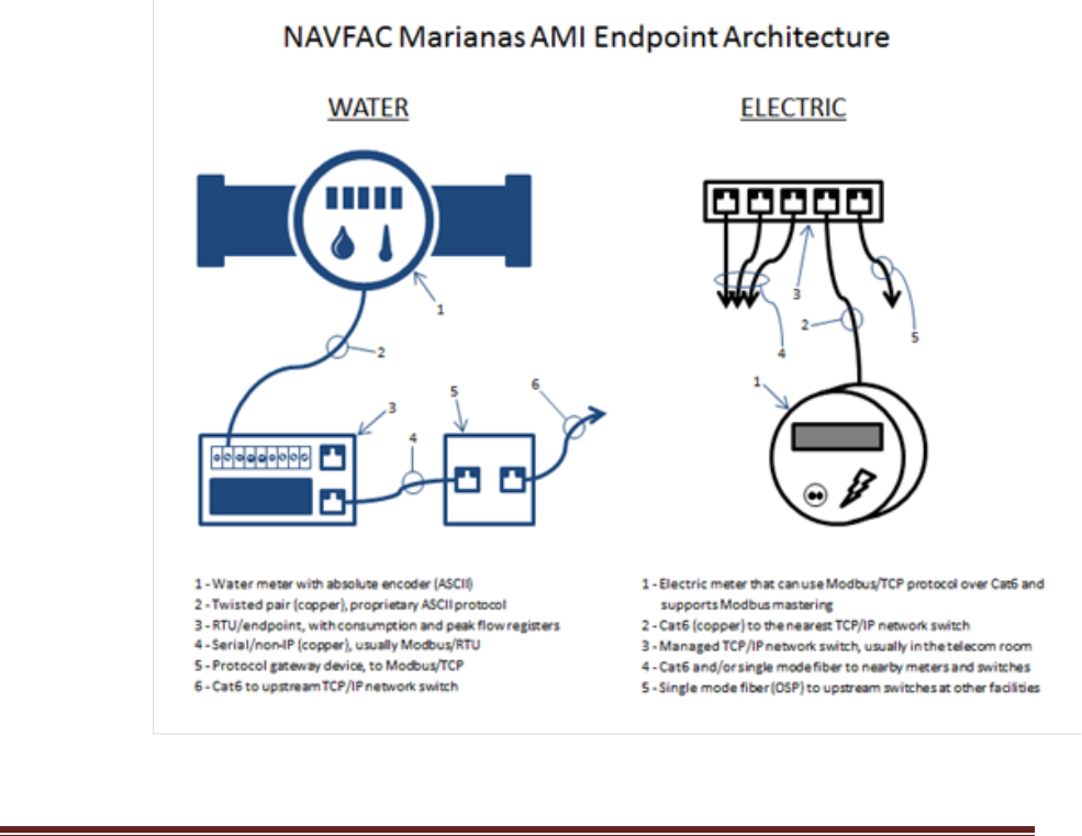
NAVFACMAR PWUC
15 November 2018
This PWUC supersedes: PWUC dated 14July2011; Revision 1 dated 02April2015 88
connections, integration into existing system and programing or re-
programing of system and databases to allow for seamless integration of
new devices or modifications into the system.
Implement electrical circuits as needed to power ICS equipment, which
also includes network switches and devices that are part of the overall
data pathway from sensors and control points to the network. Electrical
circuits for SCADA equipment shall be equipped with uninterruptible
power supply (UPS) and considered critical loads. Provide electrical power
for electricity and water metering (AMI) system equipment from the facility
electrical service entrance, at a point upstream of the electrical meter. For
water metering equipment installations that are not clearly associated with
a single facility, coordinate with the NFM ICS PM to determine the most
appropriate source of electrical power for this purpose (e.g. potable water
riser metering for ships should have electrical power sourced from the
station service transformer at the nearest wharf substation).
General AMI network architecture at system endpoints is as indicated in
the diagram below:

NAVFACMAR PWUC
15 November 2018
This PWUC supersedes: PWUC dated 14July2011; Revision 1 dated 02April2015 89
Network switches shall be managed switches, with SSH protocol
capability. Telnet protocol is not permitted, and no telnet interface may be
introduced to Navy networks. All networking equipment and control
components shall be programmable and configurable from the respective
system server to the greatest extent possible.
Configure HMIs, servers, and workstations with a dedicated main drive or
partition (C drive) with at least 150GB capacity to allow for operating
system software updates and patches independent of operational storage
requirements.
Programmable logic controllers (PLCs) shall permit removal and insertion
under power (RIUP). SCADA system mimic diagrams for all SCADA
system workstations and Human Machine Interface (HMI) displays shall
be updated to integrate all components to the greatest extent possible
such that:
a. All sensory data must be viewable in real-time
b. All specified remote device operations must be achievable.
c. Mimic diagrams must be coordinated with system operators to ensure
that appearance and use are intuitive and uniform to the greatest
extent possible.
d. False data or indications must not occur as part of normal operations
(loss of connectivity should be easily differentiated from spurious
operating conditions).
Control logic and automated routines shall be created and/or updated to
satisfy SCADA system operational requirements specific to each project.
Automated data collection and report generation processes shall be
updated to integrate added components as applicable.
IT/OT work for both hardware and software shall be performed under the
approval of CIO and PW. Contractor supplied hardware and software shall
be approved by CIO and PW in the design stage. Prior to any changes
being implemented to an existing system, or prior to new devices being
connected to an existing system, a Change Request Form shall be
submitted to the NFM ICS PM for approval by the Configuration Control
Board (CCB). The submitter may be required to be present at the CCB if
additional information is needed. The NFM ICS PM shall inform the
submitter of approval and only then may implementation of the change
begin.
Demolition of any ICS equipment shall not occur without the permission of
the NAVFAC ICS Program Manager and an approval from the CCB.

NAVFACMAR PWUC
15 November 2018
This PWUC supersedes: PWUC dated 14July2011; Revision 1 dated 02April2015 90
Projects demolishing any ICS equipment shall ensure system integrity is
maintained. Contractor shall perform all network design for modifications
and shall make all network connections, integration into existing system
and programing or re-programing of ICS and databases to allow for
seamless departure of required equipment from the system. All IT/OT
work shall be performed under the approval of CIO. If an ICS point of
presence is demolished, project shall provide termination of fiber in
handhole or other appropriate termination approved by the NAVFAC ICS
Program Manager.
Alarm reporting systems shall not interfere with SCADA system operations
and shall provide methods for controlling the impact of recurrent or long
resolution alarms on the working environment. Alarm reporting systems
shall include different levels of alarms (e.g. critical, non-critical,
informational), allow operators to view active alarms while simultaneously
interacting with the SCADA system, allow for acknowledging alarms prior
to dismissing/resolving alarms, and allow for alarm reclassification as
needed.
HMIs shall include trending/graph functions equivalent to those offered by
the existing system.
Provide at least two spares of each unique PLC device and accessory
(e.g. input/output devices). Provide at least two spare hard drives (direct
replacement) for the shared storage system. Provide at least one spare
SSD (direct replacement) for the workstations and two spare hard drives
(direct replacement) for the servers.
ICS work shall carry a minimum one year warranty, to include at least one
year of system maintenance, software/firmware updates and technical
support for all systems and software being provided under the project.
Response time for warranty and support calls shall be no longer than 24
hours, and on-site response shall be no longer than 72 hours as needed.
For major changes to the control systems, include at minimum:
a. Five days of training (8 hours per day) for up to 10 personnel to show
how to operate, maintain, troubleshoot, repair, and reconfigure/
reprogram the system. This training should include opportunity for
hands-on experience for at least 5 personnel as part of this training
requirement. Coordinate the schedule and sequence of training with
the government to ensure that Navy or BOS Contractor personnel can
attend parts of the training that are specific to their role (e.g. network
maintenance/troubleshooting).
b. Provide a SCADA operator manual with step-by-step instructions

NAVFACMAR PWUC
15 November 2018
This PWUC supersedes: PWUC dated 14July2011; Revision 1 dated 02April2015 91
(w/screenshots) showing how to perform key operational &
maintenance or troubleshooting tasks.
c. Modify operator manual based on feedback received as a result of the
training session.
Uninterrupted Power Supply (UPS) shall be provided for AMI & DDC. UPS
may be provided by the facility via back-up generator and battery room or
an individual UPS within the rack for facilities that do not have UPS power
built in.
Network switches shall be managed type with cryptographic or
comparable security feature image configured to enforce maximum
compliance with applicable STIG and Risk Management Framework
(RMF) controls. All networking equipment and control components shall
be programmable and configurable from the respective system to the
greatest extent possible.
5.3 CYBERSECURITY
The intent of the requirements in this section is to ensure that all ICS
equipment, network architectures, programming/configuration, testing,
commissioning, and documentation will facilitate system assessment and
authorization under the Department of Navy Risk Management
Framework (RMF) process. Conformance to Department of Defense
(DoD) Information Assurance (IA) requirements shall be maintained as
they related to components, installer prerequisites, performance of work,
and security procedures, in order to achieve network infrastructure that is
accreditable under the Department of Navy (DoN) Risk Management
Framework (RMF) network accreditation process. SCADA system network
accreditation documentation shall be created or updated as applicable, in
coordination with NAVFAC Marianas Utilities and Energy Management
PLC & CIO.
Personnel that are required to conduct ICS operations, maintenance,
repair, programming, configuration, installation, and/or development of
systems documentation, are required to be US citizens. Requirements for
background investigations, non-disclosure agreements, systems use
agreements, system access request forms, system change request forms,
and basic cybersecurity awareness training, are required be executed by
all personnel (as applicable) to the satisfaction of NAVFAC Marianas CIO.
Conduct all programming and script development in a secure environment
that meets the Department of Defense requirements set forth in the
standards and regulations referenced for cybersecurity in this document.

NAVFACMAR PWUC
15 November 2018
This PWUC supersedes: PWUC dated 14July2011; Revision 1 dated 02April2015 92
The Government shall be afforded the ability to monitor and witness all
installation, testing, and on-site configuration/programming work.
Applications are not permitted to be installed on Government systems
without explicit request and Government approval. Government systems
and systems provided to the Government shall not be outfitted with
hardware or software “back doors” to permit remote access. Use of flash
memory devices (including USB “thumb” drives) on Government
equipment is also prohibited. Information used in the course of systems
implementation shall be designated “For Official Use Only” (FOUO) and
shall not be disseminated without written authorization from the
Contracting Officer.
Perform cybersecurity commissioning: configure and document all
provided networking equipment in accordance with the NAVFAC Marianas
ICS Checklist in Appendix 4. All network capable devices are required to
be scanned, secured, and deemed compliant by NAVFAC CIO as prior to
being connected to an existing system.
All ICS infrastructure shall be able to pass the “assess & authorize”
process under Department of Navy Risk Management Framework (RMF)
process with minimal effort from NAVFAC CIO per the following Standards
and Regulations:
DoDD 8500.01, Cybersecurity (March 2014)
DoD Instruction 8510.01, DoD Risk Management Framework (RMF)
for DoD Information Technology (IT) (March 2014)
NIST SP 800-37 (The Risk Management Framework) (latest edition)
NIST SP 800-82 (Guide to Industrial Control Systems Security (ICS)
(latest edition)
NIST SP 800-53 (Security and Privacy Controls for Federal Information
Systems and Organizations) (latest edition)
Current guidance available at:
http://www.doncio.navy.mil/
http://csrc.nist.gov
https://www.dadms.navy.mil/
Industrial Control System Baseline Procurement Guidance. Refer to
Appendix 5.
System Authorization Access Request (SAAR) Form for Industrial Control
Systems (ICS) Standard Operating Procedures. Refer to Appendix 6.
Information System (IS) Privileged Access Agreement &
Acknowledgement (PAA) of Responsibilities. Refer to Appendix 7

NAVFACMAR PWUC
15 November 2018
This PWUC supersedes: PWUC dated 14July2011; Revision 1 dated 02April2015
Appendix 1
FORM –
UTILITY CONNECTION PERMIT APPLICATION

UTILITY CONNECTION PERMIT APPLICATION Tracking #:___________
SECTION A - GENERAL INFORMATION
1. Requesting Activity: ____________________________________________________
2. Point of Contact: _____________________ Phone Number: ___________________
3. Project Location: _______________________________________________________
4.
Type of Work: (Check all that apply.)
New Construction Building Addition Renovation
Demolition/Utility Disconnection Repair Utility Upgrade
5. Work will involve the following utilities: (Check all that apply.)
Water Sewer Electric Steam Gas
a. If Sewer is checked, will the connection be permanent or temporary?
Permanent Temporary (Proceed to question 6)
b.
If a permanent connection is required and this project involves
construction, contact the NAVFAC XXXXXX Environmental Business Line (Code
EV) to determine if CTC/CTO is required before proceeding.
6.
Work to be performed by:
ROICC Contract NAVFAC XXXXXX Maintenance Department
Contract NAVFAC XXXXXX Utilities and Energy
Management Product Line
Other: ______________________________________________________________
7. Contract Title:_________________________________________________________
Contract/J.O./MAXIMO Number: ______________Drawing Number: _____________
NAVFAC NAVFAC XXXXXX Design Activity Other:____________
NOTE: Submit a complete set of drawings with the application. Include
specifications if available.
SPECIFICATIONS INCLUDED:
YES NO
DESIGN CALCULATIONS INCLUDED:
YES NO
8. Designed by Firm/Activity:_______________________________________________
Point of Contact: _____________________________ Phone: _________________
9. Submitted by: (This is usually the Engineer in Charge (EIC) or AIC.):
Name: __________________________ Signature: ___________________________
Title: __________________ Request Date: ________ Phone: __________
10. Reviewed by:__________________________ Date:________
Approved Disapproved

SECTION B - WATER
PART A - DOMESTIC WATER SERVICE CONNECTIONS
Complete the following for all domestic water service connections to water
distribution system lines.
1. Number of Domestic Water Service Connections
(a) Existing service connections disconnected from water line __________
(b) New service connections connected to water line ___________
2. List the following for all new domestic water service connections to
water distribution system lines. See Instructions for clarification.
(a) Pipe Size(s) _________________________________________
(b) Pipe Material(s) _________________________________________
(c) Pipe Class or Schedule _________________________________________
(d) Required Capacity (in gpm) _________________________________________
(e) Required Pressure (in psi) _________________________________________
(f) Meter Size(s) _________________________________________
(g) Meter Type(s) _________________________________________
(h) Backflow Preventer (Yes/No) _________________________________________

PART B - FIRE PROTECTION (HIGH PRESSURE/NON-POTABLE) WATER SERVICE
CONNECTIONS
Complete the following for all fire protection (high pressure/non-potable)
water service connections to fire protection system lines.
1. Number of Fire Protection (High Pressure/Non-Potable) Water Service
Connections
(a) Number of existing service connections disconnected from fire
protection line _________
(b) Number of new service connections connected to fire protection line
________
2. List the following for all new fire protection (high pressure/non-
potable) water service connections to fire protection system lines. See
Instructions for clarification.
(a) Pipe Size(s) ________________________________________
(b) Pipe Material(s) ________________________________________
(c) Pipe Class or Schedule ________________________________________
(d) Required Capacity (in gpm) _________________________________________
(e) Required Pressure (in psi) _________________________________________
(f) Backflow Preventer (Yes/No) _________________________________________
SECTION C - SANITARY SEWER
PART A - SANITARY SEWER LATERAL CONNECTIONS
Complete the following information for work involving all sanitary sewer
lateral connections to sanitary sewer mains.
1. Number of Sanitary Sewer Laterals
(a) Existing laterals disconnected from sanitary sewer main __________
(b) New laterals connected to sanitary sewer main __________
2. List the following for all new sanitary sewer lateral connections. See
Instructions for clarification.
(a) Pipe Size(s) _________________________________________
(b) Pipe Material(s) _________________________________________
(c) Pipe Class or Schedule _________________________________________
(d) Total Added Design Capacity (gpm)____________________________________
3. Type of Discharge from New Sanitary Sewer Laterals
(a) Building Type: (Check all that apply)
Office Residential Housing Recreational
Warehouse Food Service Fuel Depot
Commercial Barracks Trng. Facility
Medical Industrial Aircraft Hangar
Other (Specify)________________________________
(b) Indicate below any of the operations occurring in the above
buildings: (Please check all that apply. If none of these apply, check N/A.)
N/A
Food Preparation Operations
Photo Processing or X-Ray Operations
Laboratory or Clinics
Industrial Laundry or Dry Cleaning
Printing Operations (other than copy machines for office use)
Handling or Collecting Used Oils, Solvents, Degreasers, or HW
Grease Traps

PART B - SANITARY SEWER MAINS
Complete the following information for work involving all sanitary sewer
mains.
1. Number of sanitary sewer manholes abandoned __________
2. Number of sanitary sewer manholes installed __________
3. Linear feet of sanitary sewer main abandoned __________
4. Linear feet of sanitary sewer main installed __________
5. List the following for all new sanitary sewer mains:
(a) Pipe Size(s) _____________________________________________________
(b) Pipe Material(s)_____________________________________________________
(c) Pipe Class or Schedule_______________________________________________
PART C - SANITARY SEWER PUMP STATIONS
Complete the following information for work involving all sanitary sewer pump
stations.
1. Number of sanitary sewer pump stations abandoned __________
2. Number of sanitary sewer pump stations installed __________
3. Number of pumps installed at each pump station _________________________
4. Size of each pump installed ____________________________________________
5. Attach details for pump station cut sheets, pump/ system curves, visible
and audible alarms/ channels, bypass pump connections, valve and check valve
connections, and wet well level monitoring systems.

SECTION D - ELECTRIC
PART A - PRIMARY
If the work involves the primary, complete the following:
1. System Voltage:
34.5 KV 19.9KV 13.2 KV 11.5 KV
4.16 KV 2.4 KV 2.3 KV
TRANSFORMER:
2. Installation:
New Upgrade Existing Repair
3. Type:
Pad mount Unit Substation Pole mount Station
4. Primary BIL:
200 KV 150 KV 95 KV 60 KV
Secondary BIL:
150 KV 95 KV 60 KV 30 KV
5. Rating:_______________KVA
6. Primary Connection:
Live Front Dead Front
PRIMARY CONNECTION:
7.
Overhead Underground
8. Conductor Size: ____________
Copper Aluminum
9. Type: _______________________________________
10. Insulation Level:
133% 100%
11. Point of Connection to Utility: (Check all that apply)
Existing Distrib. Switch Splice in Manhole Overhead Line Tap
New Distribution Switch Other. (Specify.) _____________________
Primary Circuit to be connected to (if known):_________________________
PART B - SECONDARY
If the work involves the secondary, complete the following:
12. Installation:
New Upgrade (Load study required) Repair
13. Transformer Load Study Performed:
Yes (Provide) No - Date expected:
14. Watt-hour meter: Form________________________________________________
Type:
Transformer rated Self-contained
4

SECTION E - STEAM
1. Purpose of new line/service: (Please check all that apply.)
Building Heating Water Heating AC/Humidity Control
Other (Specify)_______________________________________________________
2. Size of New Line_________________________________________________________
3. Size of Existing Line at Connection Point________________________________
4. Required Capacity (lbs./hr.)_____________________________________________
5. Required Pressure (psi)__________________________________________________
6. Meter model/size: _______________________________________________________
SECTION F - NATURAL GAS
1. Size of New Line_________________________________________________________
2. Size of Existing Line at Connection Point________________________________
3. Pipe Material____________________________________________________________
4. Required Capacity _______________________________________________________
5. Required Service Pressure________________________________________________
6. Meter model/size:________________________________________________________

NAVFACMAR PWUC
15 November 2018
This PWUC supersedes: PWUC dated 14July2011; Revision 1 dated 02April2015
Appendix 2
INSTRUCTIONS -
UTILITY CONNECTION PERMIT APPLICATION

UTILITY CONNECTION PERMIT INSTRUCTIONS
All questions must be answered. DO NOT LEAVE BLANKS. If a
question is not applicable, indicate it on the application. The
following are instructions for the questions on the permit
application.
SECTION A - GENERAL INFORMATION
1. Enter the name of the activity having financial
responsibility for the facility being serviced by the proposed
utility work.
2. Enter the name and phone number of an activity point of
contact responsible for the proposed utility work.
3. Enter the building number and name that is serviced by the
proposed utility work.
4. Check the categories that correspond to the majority of the
work. Abandonment of utilities should be considered demolition.
Check all that apply.
5. Check each utility being altered, added, or upgraded. For
each utility checked, complete the appropriate section in the
application.
6. Indicate the activity performing the construction or
responsible for the administration of the construction contract.
7. Indicate the project title. Enter the construction contract
number or job order number that identifies the construction
project. Enter COMNAVFACENGCOM, NAVFAC XXXXXX, and/or design
activity drawing number. Indicate the type of drawing. Attach
all existing design drawings or sketches showing proposed work
to the utility systems. Indicate if specifications are
included.
8. Enter the name of the organization, a point of contact, and
a phone number for the party responsible for the design of the
proposed work.
9. Enter the name, job title, application submission date,
phone number, and signature of the Engineer in Charge (EIC) or
Architect in Charge (AIC) completing the application.

10. Provide all design analyses performed along with drawings
and specifications.
SECTION B - WATER
PART A - DOMESTIC WATER SERVICE CONNECTIONS
1. Enter the number of:
a. Existing domestic water service connections/laterals
disconnected from the Utilities and Energy Management
Product Line-owned water distribution system involved in
the proposed work.
b. New domestic water service connections/laterals
connected to the Utilities and Energy Management Product
Line-owned water distribution system involved in the
proposed work.
2. Indicate the:
a. Size(s) of the water pipe to be tied into the domestic
water distribution system.
b. Type(s) of water pipe material to be tied into the
domestic water distribution system (e.g. ductile iron, PVC,
copper).
c. Class of water pipe that is to be tied into the
domestic water distribution system (e.g. Class 150, Class 250,
Schedule 40, and Schedule 80).
d. Design capacity for all new domestic water service
connections tying into Utilities and Energy Management Product
Line-owned water lines.
e. The design pressure for all new domestic water service
connections tying into Utilities and Energy Management Product
Line-owned water lines.
f. Size(s) of the water meter to be installed.
g. Type(s) of water meter to be installed (e.g. positive
displacement, turbine, dual flow).
h. Indicate whether or not a backflow prevention device is to
be installed.
PART B - FIRE PROTECTION (HIGH PRESSURE/NON-POTABLE) WATER
SERVICE CONNECTIONS
1. Enter the number of:
a. Existing fire protection (high pressure/non-potable)
water
service connections disconnected from the Utilities and
Energy
Management Product Line-owned fire protection water
distribution
system involved in the proposed work.
b. New fire protection (high pressure/non-potable) water
service connections connected to the Utilities and
Energy Management Product Line-owned fire protection water
distribution system involved in the proposed work.
2. Indicate the:
a. Size(s) of the water pipe to be tied into the fire
protection (high pressure/non-potable) water distribution
system.
b. The type(s) of water pipe material to be tied into the
fire protection (high pressure/non-potable) water
distribution system (e.g. ductile iron, PVC, copper).
c. The class of water pipe that is to be tied into the
fire protection (high pressure/non-potable) water
distribution system (e.g. Class 150, Class 250, Schedule
40, and Schedule 80).
d. The design capacity for all new fire protection (high
pressure/non-potable) water service connections tying into
the Utilities and Energy Management Product Line-owned fire
protection water lines.
e. The design pressure for all new fire protection (high
pressure/non-potable) water service connections tying into
the Utilities and Energy Management Product Line-owned fire
protection water lines.

f. Whether or not a backflow prevention device is to be
installed.
SECTION C – SANITARY SEWER
Note: If a permanent sewer connection is required and
construction is involved, a Certificate to Construct (CTC)/
Certificate to Operate (CTC) from Virginia Department of
Environmental Quality (VDEQ) may be necessary. Please contact
the NAVFAC XXXXXX Environmental Business Line (Code EV) to
ensure compliance with this regulation.
PART A - SANITARY SEWER LATERAL CONNECTIONS
1. Enter the number of:
a. Existing sanitary sewer laterals disconnected from the
Utilities and Energy Management Product Line-owned sanitary
sewer collection system involved in the proposed work.
b. New sanitary sewer laterals connected to the Utilities
and Energy Management Product Line-owned sanitary sewer
collection system involved in the proposed work.
2. Indicate the:
a. Size(s) of the sanitary sewer pipe to be tied into the
sanitary sewer collection system.
b. Type(s) of sanitary sewer pipe material to be tied
into the
sanitary sewer collection system (e.g. ductile iron, PVC).
c. Class or schedule of sewer pipe that is to be tied
into the sanitary sewer collection system (e.g. DR 35, DR
18, SDR 32.5, SDR 17).
d. Design capacity for all new sewer laterals connected
to Utilities and Energy Management Product Line-owned
sanitary sewer collection system.
3. Check all that apply:
a. Building types that will be served by the proposed
sanitary sewer connections. If there is a building type that
applies and is not listed, check "Other" and indicate type of
building.
b. Choices that may discharge to the sanitary sewer through
the proposed connections. If none of these apply, check
"N/A”.
PART B - SANITARY SEWER MAINS
1. Enter the number and/or quantity of:
a. Sanitary sewer manholes abandoned in the proposed work.
b. Sanitary sewer manholes installed in the proposed work.
c. In linear feet, of sanitary sewer main abandoned in the
proposed work.
d. In linear feet, of sanitary sewer main abandoned in the
proposed work.
e. In linear feet, of sanitary sewer main installed in the
proposed work.
2. Indicate the:
a. Size(s) of the sanitary sewer pipe to be used for the new
sanitary sewer main.
b. Type(s) of the sanitary sewer pipe material to be used for
the new sanitary sewer main (e.g. ductile iron, PVC).
c. Class of pipe that is to be used for the new sanitary sewer
main (e.g. DR 35, DR 18, SDR 32.5, SDR 17).
PART C - SANITARY SEWER PUMP STATIONS
1. Enter the number of:
a. Sanitary sewer pump stations abandoned in the proposed
work.

b. Sanitary sewer pump stations installed in the proposed
work.
2. Indicate the:
a. The number of pumps for each pump station installed in
the proposed work.
b. The size, including horsepower (hp) and rated flow, of
each pump for each pump station in the proposed work.
Include a manufacturer’s cut sheet and pump/system
curve for each pump.
3. Provide details for:
a. The visible and audible alarms and channels.
b. The bypass pump connections.
c. The valve and check valve specifications.
d. The wet well level monitoring system.
SECTION D - ELECTRIC
PART A - PRIMARY ELECTRICAL SYSTEM
Complete this section when any additions, modifications, or
deletions are being made to the electrical distribution system.
1. Indicate the voltage rating of the system being modified.
2. Indicate the type of work to be performed (e.g. New
transformer installation, switch removal, cable splicing,
etc.)
3. Indicate the type of equipment being installed or removed.
4. If new equipment is being installed, indicate the equipment
Basic Impulse Levels (BIL) rating (primary and secondary for
transformers).
5. Indicate the transformer rating in Kilovolt Amperes (KVA).

Indicate other equipment ratings as applicable (e.g. KVA for
transformers, amperage for switches and cables).
6. If installing a new transformer, indicate the type of
transformer primary termination being made.
7. Indicate if primary connection is overhead or underground.
8. Indicate the size of the conductors to be installed.
9. Indicate the type of conductors (e.g. ERP, XLP).
10. Indicate the cable insulation level.
11. Indicate if the connection to the utility is to be a
termination on an existing distribution switch, a primary cable
splice in a manhole, a tap to an existing overhead circuit, or a
new distribution switch. If the connection to the utility is by
some means other than those listed, check other and indicate the
proposed method. Indicate primary circuit to be tapped, if
known. Use the Utility and Energy Management Product Line
circuit designations.
PART B - SECONDARY ELECTRICAL SYSTEM
1. Indicate if work is to install a new transformer and
secondary load, or if work is to upgrade or repair an existing
transformer due to a secondary load addition.
2. Indicate if a load study has been performed on the
transformer that is having the secondary load increased. If
yes, provide a copy of the study. If no, indicate when the
study will be completed.
3. Indicate the watt-hour meter form and type to be provided.
SECTION E - STEAM
1. Check all services to be supplied by the proposed connection
and indicate the:
a. Size of the new steam line.
b. Size of the existing steam line to which service is to
be connected.
c. Design capacity for the system to be supplied by the
new connection.
d. Design pressure of the system to be supplied by the
new connection.
e. Model and size of meter being installed.

SECTION F - NATURAL GAS
1. Indicate the:
a. Pipe size of the new gas line.
b. Pipe size of the existing gas line to which service is
to be connected.
c. Pipe material of the new gas line to which service is
to be connected.
d. Design capacity for the system to be supplied by the
new connection.
e. Required service pressure for the system to be
supplied by the new connection.
f. Meter manufacturer, model, and size to be installed.

NAVFACMAR PWUC
15 November 2018
This PWUC supersedes: PWUC dated 14July2011; Revision 1 dated 02April2015
Appendix 3
FORMS & INSTRUCTIONS -
UTILITY METER CHANGE
CHANGE METER RECORD
WATER
CUSTOMER INFORMATION
ACTIVITY/ REQUESTED BY:
CUSTOMER:
NEW METER INSTALLATION
EXACT METER LOCATION
PWC ID/ METER NO.
SERIAL NO.
NAME/ TYPE METER
SIZE
DIGITS
MULTIPLIER
REGISTER
INSTALLED BY
READING
DATE/ TIME REQ./ DATE INSTALLED
NEW ROUTE NO.
ROUTE BOOK NO.
WALK SEQUENCE AFTER ROUTE NO SUB METER OF RTE
TEST PLUG TEST PLUG SIZE CHECK VLV CHECK VLV SIZE
I
BY PASS SYS BY PASS SYS SIZE VANE ADJUST
TYPE
REMARKS
METER DISCONNECT
EXACT METER LOCATION
PWC ID/ METER NO.
SERIAL NO.
NAME/ TYPE METER
SIZE
DIGITS
MULTIPLIER
REGISTER
REMOVED BY
FINAL READING
DATE/ TIME REQ./ DATE REMOVEED
ROUTE NO.
BOOK NO.
WALK SEQUENCE AFTER ROUTE NO SUB METER OF RTE
REMARKS
______________________________ _________________________________
Prepared By Approved By

CHANGE METER RECORD
POWER
INSTALLED
ACTIVITY/ REQUESTED BY
EXACT METER LOCATION
PWC ID/ METER NO. SERIAL NO. NAME/ TYPE METER SIZE
WIRE PHASE AMP VOLT/ VOLTAGE RATING
CT PT
MULTIPLIER FROM
MULTIPLIER TO
SUBMETER/ RECORD NO. LOCATION OF SUB BY PASS OPEN
SET BY READING DATE/ TIME REQ./ DATE INSTALLED
NEW ROUTE NO. ROUTE BOOK NO. DIGITS
PLACEMENT/ LOCATION OF METER
REMOVED
ACTIVITY/ REQUESTED BY
EXACT METER LOCATION
PWC ID/ METER NO. SERIAL NO. NAME/ TYPE METER SIZE
WIRE PHASE AMP VOLT/ VOLTAGE RATING
CT PT
MULTIPLIER FROM
MULTIPLIER TO
SUBMETER/ RECORD NO. LOCATION OF SUB BY PASS OPEN
REMOVED BY READING DATE/ TIME REQ./ DATE REMOVED
ROUTE NO. ROUTE BOOK NO. DIGITS
PLACEMENT/ LOCATION OF METER
REMARKS
Prepared By Approved By
Page 1 of 1
Last Revised: MAR 2017

CHANGE METER RECORD
POWER
INSTALLED
ACTIVITY/ REQUESTED BY:
For AMI electric meters, coordinate w/ ICS for
the meter point ID No. For regular electric
meters - Coordinate w/ govt project oversight
to determine which activity the project belongs
to.
EXACT METER LOCATION
Provide equipment ID No. & address
PWC ID/ METER NO.
To be filled-up by BOSC Annex
1602 Meter/Relay
SERIAL NO.
Meter Device S/N
NAME/ TYPE METER
Meter Form (e.g. 5S, 9S, 36S &
etc.)
SIZE
Meter number of terminals (check the
meter’s back side
)
WIRE
e.g. 3-Wire Delta or
4-wire WYE, etc
PHASE
Single Phase or Three
Phase
AMP
Applicable meter’s amperage
e.g.2.5 A
VOLT/ VOLTAGE RATING
Applicable Transformer’s Secondary
Voltage or Service Voltage
CT
N/A if not applicable, otherwise
indicate Current Transformer
Ratio (CTR)
PT
N/A if not applicable,
otherwise indicate
applicable Potential
Transformer ratio
MULTIPLIER FROM
1.0 for AMI Electric meters,
otherwise quotient of the
applicable CTR
MULTIPLIER TO
1.0 for AMI Electric meters, otherwise
quotient of the CTR
SUBMETER/ RECORD NO.
Upstream KWH meter
LOCATION OF SUB
Facility number or Bldg.,
number where the
upstream KWH meter is
located
BY PASS OPEN
N/A if not applicable
SET BY
Contractors Name
READING
Initial reading of the kWh meter
DATE/ TIME REQ./ DATE INSTALLED
Date/Time when kWh meter is
energized
NEW ROUTE NO.
To be filled-up by BOSC Annex 1602 Meter/ Relay
ROUTE BOOK NO.
To be filled-up by BOSC Annex
1602 Meter/Relay
DIGITS
Refer to kWh meter’s Product Data and
provide “ Number” of digits
PLACEMENT/ LOCATION OF METER
REMOVED
ACTIVITY/ REQUESTED BY
EXACT METER LOCATION
PWC ID/ METER NO. SERIAL NO.
NAME/ TYPE METER SIZE
WIRE PHASE
AMP VOLT/ VOLTAGE RATING
CT PT
MULTIPLIER FROM MULTIPLIER TO
SUBMETER/ RECORD NO. LOCATION OF SUB
BY PASS OPEN
REMOVED BY
READING DATE/ TIME REQ./ DATE REMOVED

ROUTE NO.
ROUTE BOOK NO. DIGITS
PLACEMENT/ LOCATION OF METER
REMARKS
Indicate pertinent information (e.g. PWD UEM
performed Field Inspection; BOSC Meter/Relay
performed Bench Testing; kWh meter is for
Temporary use; kWh meter/Smart meter is
Factory programmed, etc.)
______________________________ _________________________________
Prepared By Approved By

CHANGE METER RECORD
WATER
CUSTOMER INFORMATION
ACTIVITY/ REQUESTED BY:
Coordinate w/ government project oversight to determine which activity the project belongs to.
CUSTOMER:
End user, who meter will be billed/was billed to. To be provided by Government oversight team.
NEW METER INSTALLATION
EXACT METER LOCATION
Provide equipment ID No. & address
PWC ID/ METER NO.
To be filled-up by BOS Contractor
SERIAL NO.
Meter Device S/N
NAME/ TYPE METER
Make & Meter type
SIZE
Meter size
DIGITS
Number of digits
MULTIPLIER
Ex, 10X, 100X, etc.
REGISTER
US Gallons, Liters
INSTALLED BY
Contractors Name
READING
Initial reading of the water meter
DATE/ TIME REQ./ DATE INSTALLED
Date/Time when water meter is
installed
NEW ROUTE NO.
To be filled-up by BOS Contractor
ROUTE BOOK NO.
To be filled-up by BOS Contractor
WALK SEQUENCE
To be filled-up by BOS Contractor
AFTER ROUTE NO
To be filled-up by BOS Contractor
SUB METER OF RTE
To be filled-up by BOS Contractor
TEST PLUG
If Applicable
TEST PLUG SIZE
If Applicable
CHECK VLV
If Applicable
CHECK VLV SIZE
If Applicable
BY PASS SYS
If Applicable
BY PASS SYS SIZE
If Applicable
VANE ADJUST
TYPE
If Applicable
REMARKS
METER DISCONNECTION
EXACT METER LOCATION
Provide equipment ID No. & address
PWC ID/ METER NO.
To be filled-up by BOS Contractor
SERIAL NO.
Meter Device S/N
NAME/ TYPE METER
Make & Meter type
SIZE
Meter size
DIGITS
Number of digits
MULTIPLIER
Ex, 10X, 100X, etc.
REGISTER
US Gallons, Liters
REMOVED BY
Contractors Name
FINAL READING
Final reading of the water meter
DATE/ TIME REQ./ DATE REMOVEED
Date/Time when water meter is
removed
ROUTE NO.
To be filled-up by BOS Contractor
BOOK NO.
To be filled-up by BOS Contractor
WALK SEQUENCE
To be filled-up by BOS Contractor
AFTER ROUTE NO
To be filled-up by BOS Contractor
SUB METER OF RTE
To be filled-up by BOS Contractor
REMARKS
______________________________ _________________________________
Prepared By Approved By

NAVFACMAR PWUC
15 November 2018
This PWUC supersedes: PWUC dated 14July2011; Revision 1 dated 02April2015
Appendix 4
FORM –
NAVFAC MARIANAS ICS CHECKLIST

NOTES/COMMENTS DATE
Finished
CTR
Init's
GOV
Witness
DESCRIPTION
Remove all Software and Services not required for operation and/or maintenance of the product :
If removal is not technically feasible, then disable software not required for the operation and/or maintenance of the product. This removal shall not impede the primary function of the
product. If software that is not required cannot be removed or disabled, document a specific explanation and provide risk mitigating recommendations and/or specific technical justification.
Provide documentation on what is removed and/or disabled. The software/service to be removed and/or disabled shall include, but not be limited to:
• Games
• Device drivers for product components not procured/delivered
• Messaging services (e.g., email, instant messenger, peer-to-peer file sharing)
• Source code
• Software compilers in user workstations and servers
• Software compilers for programming languages that are not used in the energy
delivery system
• Unused networking and communications protocols
• Unused administrative utilities, diagnostics, network management, and system
management functions
• Backups of files, databases, and programs used only during system development
• All unused data and configuration files
Provide documentation of software/firmware that supports the product, including scripts and/or macros, run time configuration files and interpreters, databases and tables, and all other
included software (identifying versions, revisions, and/or patch levels, as delivered). The listing shall include all ports and authorized services required for normal operation, emergency
operation, or troubleshooting.
Remove and/or disable, through software, physical disconnection, or engineered barriers, all services and/or ports in the procured product not required for normal operation, emergency
operations, or troubleshooting. This shall include communication ports and physical input/output ports (e.g., USB docking ports, CD/DVD drives, video ports, and serial ports). Provide
documentation of disabled ports, connectors, and interfaces.
Configure the product to allow the ability to re-enable ports and/or services if they are disabled by software.
Disclose the existence of all known methods for bypassing computer authentication in the product, often referred to as backdoors, and provide written documentation that all such backdoors
created have been permanently deleted from the system.
Provide summary documentation of the procured product’s security features and security-focused instructions on product maintenance, support, and reconfiguration of default settings.
Access Control
Implement a warning banner on terminal interfaces that conforms to DoD warning banner guidelines
Configure each component of the product to operate using the principle of least privilege. This includes operating system permissions, file access, user accounts, application-to-application
communications, and energy delivery system services.
Provide user accounts with configurable access and permissions associated with one or more organizationally defined user role(s), where roles are used.
Provide a system administration mechanism for changing user(s’) role (e.g., group) associations.
Configure the product such that when a session or interprocess communication is initiated from a less privileged application, access shall be limited and enforced at the more critical side.
Provide a method for protecting against unauthorized privilege escalation.
Document options for defining access and security permissions, user accounts, and applications with associated roles. Configure these options, as specified.
Prevent unauthorized changes to the Basic Input/Output System (BIOS) and other firmware and document if not feasible, provide mitigation recommendations.
Verify and provide documentation for the procured product, attesting that unauthorized logging devices are not installed (e.g., key loggers, cameras, and microphones).
Account Management
Document all accounts (including, but not limited to, generic and/or default) that need to be active for proper operation of the product.
Change default account settings to specific settings (e.g., length, complexity, history, and configurations) provided by government rep. Changed account information will not be published.
All new account information will be provided by a protected mechanism.
Remove or disable any accounts that are not needed for normal or maintenance operations of the energy delivery system.
Accounts for emergency operations shall be placed in a highly secure configuration and documentation on their configuration.
Session Management
Configure system to disallow multiple concurrent logins using the same authentication credentials, allow applications to retain login information between sessions, provide any auto-fill
functionality during login, or allow anonymous logins.
Implement account-based and group-based configurable session-based logout and timeout settings (e.g., alarms and human-machine interfaces).
Authentication/Password Policy and Management
NAVFAC MARIANAS ICS CHECKLIST v2.1 FOR [SYSTEM NAME]
FOUOͲFOROFFICIALUSEONLYͲDONOTDISTRIBUTE

Document the levels, methods, and capabilities for authentication and authorization. Deliver a product that adheres to standard authentication protocols.
Implement a configurable account password management system that allows for, but is not limited to, the following:
• Changes to passwords (including default passwords)
• Selection of password length
• Frequency of change
• Setting of required password complexity
• Number of login attempts prior to lockout
• Inactive session logout
• Screen lock by application
• Comparison to a library of forbidden strings
• Derivative use of the user name
• Denial of repeated or recycled use of the same password
Ensure/verify that passwords are not stored within or around the system in clear text, and not hardcoded into software or scripts.
Implement a centralized and local account management interface.
Implement a secure method of authentication (e.g., strong two-factor authentication) to allow for single sign-on authentication to a suite of applications.
Ensure/verify the protection of key files and access control lists used by the authentication system from non-administrative user read, write, and delete access. The authentication system must
resolve each individual user’s credentials, roles, and authorizations to each application.
Provide documentation on configuring a single-sign-on system, as well as documentation showing equivalent results in running validation tests against the direct login and the single sign-on.
Logging and Auditing
Implement logging capabilities or the ability to support the existing logging system. Logging capabilities shall be configurable by the government and support the governments security
auditing requirements. As specified by the government, the procured product shall cover the following events, at a minimum (as appropriate to their function):
• Information requests and server responses
• Successful and unsuccessful authentication and access attempts
• Account changes
• Privileged use
• Application start-up and shutdown
• Application failures
• Major application configuration changes
Implement standard time synchronization in the procured product (e.g., Global Positioning System [GPS], Network Time Protocol [NTP], and IEEE 1508-2008). If not providing standard
time synchronization and is providing an alternate authoritative time source, the procured product shall be configured to synchronize to that authoritative time source.
Ensure/verify that time stamp audit trails and log files are automatically generated, as specified by the Acquirer.
Provide a list of all log management capabilities that the product is capable of generating and the format of those logs. This list shall identify which of those logs are enabled by default.
Communication Restrictions
Document all remote access entry pathways and ensure that they can be enabled or disabled by the Acquirer as needed.
Ensure/verify that a method is provided for managing the network components of the procured product and changing configurations, including hardware and software configurations (e.g.,
addressing schemes).
Verify and document how the network configuration management interface is secured.
Malware Detection and Protection
Implement the capability to automatically scan any removable media that is introduced to the product being acquired.
Implement both of the following:
• Provide a host-based malware detection capability. Quarantine (instead of automatically deleting) suspected infected files. Provide an updating scheme for malware signatures. Test and
confirm compatibility of malware detection application patches and upgrades.
• Provide an application whitelisting solution that is tested, validated, and documented that shall only permit approved applications to run.
Validate that cybersecurity services running on the procured product (e.g., virus checking and malware detection) do not conflict with other such services running on the procured product.
Reliability and Adherence to Standards
Verify that the addition of security features does not adversely affect connectivity, latency, bandwidth, response time, and throughput specified.
Physical Access System Components
Provide lockable or locking enclosures or rooms for energy delivery systems and system components (e.g., servers, clients, and networking hardware) and for the systems used to manage and
control physical access (e.g., servers, lock controllers, and alarm control panels).
Provide a method for tamper detection on lockable or locking enclosures. If a physical security and monitoring system is used, tamper detection shall be compatible.
Change locks, locking codes, keycards, and any other keyed entrances or provide the tools and instructions for making these changes.
FOUOͲFOROFFICIALUSEONLYͲDONOTDISTRIBUTE

Verify that physical security features do not hamper energy delivery system operations.
Reprogram codes (e.g., remove default codes) on provided locks and locking devices so that the codes/passwords are unique and do not repeat codes used in the past. Convey all
codes/passwords to the government at system operational turnover.
General Wireless Technology Provisions
Document specific protocols and other detailed information required for wireless devices to communicate with the control network, including other wireless equipment that can communicate
with the supplied devices.
Document use, capabilities, and limits for the wireless devices.
Document the power and frequency requirements of the wireless devices (e.g., microwave devices meet the frequency requirements of Generic Requirements [GR]-63 Network Equipment
Building System [NEBS] and GR-1089).
Document the range of the wireless devices and verify that the range of communications is minimized to both meet the needs of the proposed deployment and reduce the possibility of signal
interception from outside the designated security perimeter.
Document that the wireless technology and associated devices comply with standard operational and security requirements specified in applicable wireless standard(s) or specification(s) (e.g.
applicable IEEE standards, such as 802.11).
Document the configuration control options that enable varying of the security level of the devices.
Recommend alarm settings in accordance with the needs of the system, and implement in accordance with government direction.
Patch Management and Updates
Verify and document that all products (including third-party hardware, software, firmware, and services) have appropriate updates and patches installed.
______________________________________________________________________ __________
SIGNATURE DATE
I, [name of contractor QC Manager], attest that all of the items on this checklist have been verified and witnessed, and that comprehensive
information for each item has been provided as applicable
FOUOͲFOROFFICIALUSEONLYͲDONOTDISTRIBUTE

NAVFACMAR PWUC
15 November 2018
This PWUC supersedes: PWUC dated 14July2011; Revision 1 dated 02April2015
Appendix 5
INDUSTRIAL CONTROL SYSTEM BASELINE
PROCUREMENT GUIDANCE
Version 2.1

ʹǤͳ
ͶȀ
ʹͶʹͲͳ
Theobjectiveofthisdocumentistoprovidecontractlanguageandrequirementsthatcanbeusedin
NAVFACconstructionprocurementsofIndustrialControlsSystemsandpartsofthosesystems.Within
NAVFAC,thesesystemsgenerallyconsistofutilitySCADAsystems,buildingDDCsystems,andAMI
systems,althoughmuchofthis
languagecanbeusedtosupportprocurementofotherkindsof
cybersecuresystems(nonͲstandardIT).
ThelanguageinthisdocumentshouldbemodifiedasneededandinsertedintoRFPsandothercontract
documentswhereappropriate.Coordinatethislanguageandotherrequirementsofthisnaturewiththe
localCIO4branchto
ensurethatthelanguage(asmodifiedandinserted)issufficienttomeetCIO4
expectations,sincemuchofthecybersecurityassessmentand authorization processwillbeconducted
byCIO4.
Apartfromtheprovidedlanguage,thechecklistattachmentisforsysteminstallerstoreviewand
coordinatewithCIO4support(orCMEwho
isqualifiedandtrainedforthispur pose)duringinstallation
andtesting.Thechecklistisintendedtobeacontractattachment.AnExcelformatcopyshouldbe
giventothewinningbiddersothattheactualspreadsheetcanbeannotatedwithcommentsand
validationnotesaspertheinstructionsincludedinthe
languagebelow.
GeneralGuidance
TheintentofthisprojectisforallIndustrialControlsSystems(ICS)equipment,networkarchitectures,
programming/configuration,testing,commissioning,anddocumentationtobeassessedandauthorized
undertheDepartmentofNavyRiskManagementFramework(RMF)processperthemostcurrent
versionsofthefollowingstandardsandregulations:
x DoDI8500.01,Cybersecurity
x DoDI
8510.01,DoDRiskManagementFramework(RMF)forDoDInformationTechnology(IT)
x NISTSP800Ͳ37,TheRiskManagementFramework
x NISTSP800Ͳ82,GuidetoIndustrialControlSystems(ICS)Security
x NISTSP800Ͳ53,SecurityandPrivacyControlsforFederalInformationSystemsandOrganizations
Currentguidanceisavailableat:
x http://www.doncio.navy.mil/
x https://www.dadms.navy.mil/
x http://csrc.nist.gov/publications/PubsSPs.html
Forallprovidedsystemsandpartsofsystems,theGovernmentshallbeaffordedthecapabilityto
seamlesslyandefficientlyunderstand,operate,test,maintain,securefromunauthorizedaccess,
diagnoseandtroubleshootproblems,andrecoverfromrunͲtimeerrors.

Allprovidedequipmentandsoftwareshallbecurrentlymarketedproducts,notcurrentlyscheduledfor
endoflifeorobsolescence,toensuresystemsustainability.Whereolderversionsofsoftwareare
providedduetoincompatibilityconcernsbetwee ndifferentversions,providetheGovernmentwiththe
means(licenses,installdisks,andanyotherinstallation
materials)tofullyupdatetheprovidedsoftware
tothelatestmarkete dversion.Hardwa reandsoftwareproductsforsystemsnetworkingshouldhave
beenevaluatedandaccreditedatalicensed/approvedevaluationfacilityandli stedasbeingin
conformancetotheCommonCriteriaforITSecurityEvaluation(ISOStandard15408,visit
https://www.niapͲccevs.orgfor
moreinformation);productsshowntobeintheevaluationprocessfor
thispurposeareacceptable.Operatingsystemsandmalware/antivirusprotectionapplication(s)must
alsobeapprovedforusebytheDepartmentoftheNavyintheDoNApplicationsandDatabase
ManagementSystem(https://www.dadms.navy.mil).Allsoftwarelicensesarerequiredtobein
the
nameoftheDepartmentoftheNavy.
Legacydevicesthatarenotrequiredinthenewsystemconfigurationshallbedisconnected,removed
andturnedovertothegovernmentunlessotherwiseindicated.
ContractorPersonnelRequirements
Personnelinstallingand/orinteractingwithneworexistingsystemshardwareandsoftwarearerequired
tobeUnitedStatescitizens.PersonnelrequestingaccesstoexistingNavysystemsforthepurposeof
installingnewsoftware,programming/configuring software,ormodifyingcodeforexistingsoftwareare
requiredtohaveafavorablesecuritybackgroundcheckin
accordancewithITͲIIdesignation,perSECNAV
MͲ5510.30.
IndividualsdevelopingorusingSecurityControlsdocumentation,orotherdocuments thatare
designated“ForOfficialUseOnly”(FOUO),willberequiredtocompleteandsubmitasignedNonͲ
DisclosureandDataHandlingAgreementforFOUOinformation.Individualsinstallingand/orinteracting
with
neworexistingsystemsequipmentwillberequiredtosubmitdocumentationshowingcompliance
withthefollowingadditionalrequirements:
a) Filloutandsign/submittheNAVFACMarianasSCADAChangeRequestForm(asneeded)
b) Filloutandsign/submittheICSSAARͲNSystemsAccessAuthorizationRequestForms
c) Filloutand
sign/submittheICSIAAddendum
d) FinishDoDCyberAwarenesstraining(http://iase.disa.mil/eta/cyberchallenge/launchPage.htm)
e) Filloutandsign/submittheNAVFACMarianasICSPrivilegedAccessForm(forelevated
privileges,suchasforadministratororprogrammertasks)
Individualsengagedinsystemsdesign,programming,andconfigurationactivities,shallpossessatleast3
yearsofdocumented
experienceinimplementingsimilarsystems,specificprojectexperiencethatis
relevanttothetypeofworkbeingdoneonthesystem,andmanufacturertrainingintheuseand
programmingofanycontrolsdevicesbeinginstalled.
InstallationRequirements

Existingsystemsshallremainoperableandservicesshallnotbeinterruptedduringtheconstruction
processtothegreatestextentpossibleunlessotherwiseindicated.Coordinateconstructionphasingin
theprojectschedule/connection ortieͲinplanandsafetyplanwiththegovernmentandthesystem
operatorforapprovalpriortostartofconstruction.
Systemsmaybelocatedwithincontrolledaccessareas.Accessrequestproceduresandrequirements
foraccessmustbefollowedfortheselocations.Escortsmaybenecessaryinmanyifnotall
circumstances.TheContractorwillberesponsiblefor coordinatingaccessandescorts withthe
Government.
TheGovernmentshallbeafforded
theabilitytomonitorandwitnessallinstallation,testing,andonͲsite
configuration/programmingwork.
Duetorigorousnetworksecurityrequirements,accesstoexistingsystemsisnotpermittedwithoutthe
individual’sconsenttoasystemsuseagreement.Ingeneral,noapplicationsmaybeinstalledon
governmentsystemswithoutexplicitrequestand
Governmentapproval.Governmentsystemsand
systemsprovidedtotheGovernmentshallnotbeoutfittedwithhardwareorsoftware“backdoors”to
permitremoteaccess.Useofflashmemorydevices(includingUSB“thumb”drives)onGovernment
equipmentisalsoprohibited.Informationusedinthecourseofsystemsimplementa tion shallbe
designated“For
OfficialUseOnly”(FOUO)andshallnotbedisseminatedwithoutwrittenauthorization
fromtheContractingOfficer.
Programmingandconfigurationrequirements
Forprogrammableorconfigurableinterfaces,coordinaterequirementswiththesystemoperatorand
submitdraftinterfacediagrams(andmimicdiagramsasapplicable)anddescriptionsforGove rnment
approvaltoensurecompliancewithsystemoperatorrequirements.
ConfigureallprovidedsystemsandpartsofsystemsasneededtocomplywiththeNAVFACMarianasICS
Checklist.
Allprogrammedcodeandscriptsdevelopedunderthisprojectshallbedocumentedandcontain
annotationswithinthecodestructureinaccordancewithindustrybestpractices,foreaseof
understandingintroubleshootingoradapting.Codeshallbeorganizedintologicalsections,clearly
defined,withcomments indicatingthefunction ofeach
section,includinganyexpectedinputs,outputs,
andcallingfunctions.Modificationstoexistingcodeshallbeproperlyannotated,includingdateof
change,reasonforchange,anychangestoexpectedforinputsoroutputs.Allscriptsandsourcecode
shallbedeliveredtotheGovernmentinreadableformataspartofcloseͲout
submittals,unlessthis
requirementiswaivedbyNAVFACMarianasCIO.Conductcodereviewsatregularintervalstoensure
qualityandreducethelikelihoodoferrorsandsecurityvulnerabilities.Documenttheresultsofthis
processandprovideforGovernmentreviewuponrequest.

Systemswithprogrammableinterfacesshallbeconfiguredwithadequateinterfacesandmimic
diagrams(asapplicable)foroperatorstoeasilyviewandunderstandallavailabledataandsystem
conditions.Mimicdiagramsshallbearresemblancetoactualequipmentandprocesslayouts tothe
satisfactionoftheGovernmentandthesystemoperators.Wherepossible,
agraphicalnetwork
analysis/statusinterfaceshallbeprovidedtoallowfortroubleshootingandverificationofnetwork
conditions.Interfacesshallnotdisplayfalseinformation,andshouldaccuratelyconveyfaultconditions
suchaswhennetworkconnectivityforparticulardeviceshasbeenlost.
Allcodeprogrammingandscriptdevelopmentu nderthisprojectshall
beconductedinasecure
environmentthatmeetstheDepartmentofDefenserequirementssetforthintheStandards and
Regulationsreferencedforcybersecurityinthisdocument.
Copiesofcodemodifiedorproducedunderthiscontractshallonlyberetainedwhileundera
sustainmentorsupportcontractwiththeGovernment,and
shallonlybeusedforthepurposes
describedwithinthebounds oftheagreementunlessexpresslyauthorizedinwritingbyNAVFAC
MarianasCIO.Codemodifiedorgeneratedunderthiscontractshallbedisposedofasdescribedinthe
NonͲdisclosureandDataHandlingagreement.
Testingandcommissioningrequirements
RequestaneditableversionoftheNAVFACMarianasICSChecklistfromthegovernment,andannotate
withinformationrequiredbythechecklist,aswellasthedateandnameofthegovernment
representativewhowitnessedvalidationofeachitem.(Demonstratetothesatisfactionofthe
governmentthatsystemcomponentsareincompliance
withtheNAVFACMarianasICSChecklistand
SecurityControlsdocumentationpriortocommissioning.Facilitategovernmenttestingofthesystem
vianetworkscansandSecurityTemplateImplementationGuide(STIG)testing,andprovidesupportfor
interpretingscanandSTIGtestresultsasneeded).ShowtothesatisfactionoftheGovernmentthatall
providedsystemcomponentsareincompliancewiththeNAVFACMarianasICSChecklistandSecurity
Controlsdocumentationpriortocommissioning.
Conductsystemstestingandverification,witnessedbythegovernmentanditssystemoperatoraseach
systemcomponentisbroughtonlineandcommissioned.Systemstestingandverificationshallshowvia
operatorinterface(s)
thatsystemstatusesandmeasurementsarereportedaccurately,controlsarefully
operable,andprogramming/configurationconformstostatementofworkandoperatorrequirements.
Notifythecontractingofficerforthwithofanyequipmentorsystemmalfunctionsencounteredbeforeor
duringtestingthatareoutsidethescopeofwork.Detailedtestprocedures,results,date/time,
witnessing
personnel,andotherconditionsasapplicableshallbedocumentedforsubmissionaspartof
closeͲoutsubmittals.
Trainingrequirements
ProvideonͲsitetrainingforlengthoftimeandpersonnelasindicatedtoshowhowtooperate,maintain,
troubleshoot,repair,andreconfigure/reprogramthesystem.Thistrainingshouldincludeopportunity
forhandsͲonexperienceaspartofthistrainingrequirement.Developandprovideanoperatormanual

withstepͲbyͲstepinstructions(w/screenshots)showinghowtoperformkeyoperational&
maintenance/troubleshootingtasks.Modifytheoperatormanualbasedonfeedbackreceivedasa
resultofthetrainingsession.
Evaluationfactors
Aspartofthetechnicalnarr ative,detailprogrammercertificationandtrainingrequirements,and
provideaplandescribinghowcoderev iewswillbeconductedanddocumentedforGovernmentreview
inawaythatisverifiable(automatedcodereviewtoolswithsummaryreportprintoutsare
recommended).Describesoftwaredevelopmentpracticesandstandards applied
tocontrolsystem
softwareandfirmwarethatiswrittenbytheofferorand/oranyplannedsubcontractors.Provide
detailedinformationaboutqualityassuranceprogramsthatareinplacefortheprovidedcontrolsystem
softwareandfirmware,aswellasqualitycontroltestingmethodsandresults,alsoincludingunresolved
vulnerabilitiesandrecommended
mitigationmeasures.Qualitycontroltestingshouldincludefuzz
testing,statictesting,dynamictesting,andpenetrationtesting,aswellasuseofpositiveand
appropriatenegativeteststoverifythattheprocuredproductoperatesinaccordancewith
requirementsandwithoutextrafunctionality,aswellasmonitoringforunexpectedorundesirable
behaviorduring
thesetests.IndicateapproachandcapabilitytoremediatenewlyreportedzeroͲday
vulnerabilities.
Submittalrequirements
OperatorManual:provideboundhardcopiesasindicatedfortrainingpurposes.ProvidefinalOperator
Manuals(includingmodificationsbaseduponfeedback)inconjunctionwithOMSIsubmittalsforall
installedequipmentinaccordancewithspecification017824.0520.Alldocumentsshallbesubmitted
innative(editable)andPDFformatsonCDͲR
orDVDͲRinthequantitiesindicated.
Sustainmentmaterials:providethefollowingforeveryPLC,RTU,SupervisoryController,orother
networkͲcapable(whethernetworkedornotupondelivery)controldevice,organizedbydeviceand
deliveredonCDͲRorDVDͲRinconjunctionwithOMSIsubmittals:
a) Originalfirmware
b)
Originalfirmwarehash
c) SOPforapplicationoffirmwareupdates/patches
d) POCorwebsiteforfirmwareupdates/patches
e) Countofinterfacesandtypes
f) Protocolsinuse,perinterface
g) Configurationfile
h) SOPforconfiguration
SecurityControlsdocuments:editexistingdocumentationwhereapplicable;otherwiseprovidenew
documentationasdescribed.
ProvidedraftSystemsAuthorizationdocuments,AccessControls
Summary,AuditingControlsSummary,ConfigurationManagementPlan,ContingencyPlan,Security
FeaturesGuide,VulnerabilityManagementPlan,andMaintenancePlandocuments,aswellas
DocumentedStatementsalongwithallformaldesignsubmittals,completewithallinformationavailable

atthetimeofthesubmittal.Provideadocumentchangelogandoutlineormarksectionsofdocuments
thathavebeenchangedfromoriginalsandfromeachprevioussubmittal.ProvidefinalSecurityControls
documentsinconjunctionwithAsͲBuiltssubmittals,andadditionallyincludethecompletedNAVFAC
MarianasICSChecklist.Requesteditabletemplates
forhardwareandsoftwarelistsfromthe
Government,aswellasanexamplenetworkdiagramforuseasguidance.Hardwareandsoftwarelists
shallbeinformatseditableviaMicrosoftExcel2010.Networkdiagramsshallbeinformatse ditablevia
AutoCAD2010.Alldocumentsshallbesubmittedinnative(editable)
andPDFformatsonCDͲRorDVDͲR
inthequantitiesindicated.
SystemAuthorizationDocuments
a) Drafthardwarelist(includethefollowingforeachdevice):
Ǧ Manufacturer,
Ǧ Productline,
Ǧ Model(andspecificvariantifapplicable),
Ǧ Producttype,
Ǧ Location(installation/specialarea/building/floor/room),
Ǧ keytechnicalratings(e.g.memory),
Ǧ Serialnumber,
Ǧ MACaddresses,
Ǧ IPaddresses,
Ǧ UniqueNavyidentifierorbarcode(if
assigned)
Ǧ Operatingsystemsoftware(cross
referencewithsoftwarelist)
Ǧ Applicationsoftware(crossreferencewithsoftwarelist)
Ǧ Networkconnectionsandtypes(crossreferencewithnetworkdiagram)
b) SoftwareList(includethefollowingforallsoftware):
Ǧ Manufacturer
Ǧ Version/subversion,
Ǧ Location/device,
Ǧ Usednetworkports/protocols/services.
(Bothhardwareand
softwarelistsshouldalsoincludeCommonCriteriaEALstatus,DADMSentry
number,andOS/IOS/Firmwareversion(s)asapplicable).
c) Networkdiagram
Ǧ Networkdiagrammustshowequipmentlocations,names,models,andIPaddresseson
networkcommunicationsschematic.
AccessControlsSummary
a) Informationonsoftwareaccesscontrols,portcontrol,andprotection.
b) Systemuserrolesimplementedbyapplicationandaccessprivilegesassignedbydefaulttoeachrole.
Ifprivilegescanbeaddedto,orremovedfrom,arole,sospecify.
c) Detailsonsystemlogon,includingdenialafterthree(3)invalidattempts,howtodelay
subsequent
logons.
d) DetailsonprivilegedaccountsͲwhoshouldhavethemandwhenaretheyused.
e) Detailsonkindsofaccounts,theirassociatedprivileges,whichrolesshouldhaveaccess,andsoonͲ
servers,wireless,equipment,meters.
f) UserID/Passwordrequirementsand/orPKIrequirementsincludingdetailson
shadowing,
enforcementofpasswordstrength,encryption
ofpasswords.
g) Detailsofsystemlibrarystructureandwhatrolesshouldbeallowedwhataccessprivilegestolibrary
components.
h) Detailsonremote(wireless)accessbylaptopsorserverstometerand/orradiodata.

AuditingControlsSummary
a) Detailsonauditingcontrolsandauditing(creationofsystemaudittrailforuseraccountability).
ConfigurationManagementPlan
a) Vendorconfigurationmanagementplan.
b) Informationrequiredtoverifyandtestallpatchesandupgradespriortodeployment,including
resources,capabilities,andcoordinationasrequiredwithanytestproceduresrunatvendorlabs.
ContingencyPlan
a) RestorationProcedures–Guidanceonrestoringvendorsoftware&hardwareincludingguidanceto
helpdeterminepriorityforrestoration.
b) Startup&ShutdownProcedures–Detailsofsysteminitialization,shutdown/abortsdesignedto
ensuresecuresystemstate.
SecurityFeaturesGuide
a) ListanddiscussionofallsecurityfeaturesofVendorhardwareandsoftware.
b) Documentuseofmobilecode(e.g.scripts,suchasJava)andprotectionsinplacetopreventmalicious
contentfromusingassociatedruntimesystems.
c) DocumentedFIPS140Ͳ2validatedcryptography(orequivalent)compliance.
VulnerabilityManagementPlan
a) Informationrequiredtoverifyandtestallpatchesandupgradespriortodeployment,including
resources,capabilities,andcoordinationasrequiredwithanytestproceduresrunatvendorlabs.
b) Securityissuesassociatedwithimplementationandmaintenanceoftheapplication.
c) CybersecurityPOCforresolutionofCybersecurityissuespostaccreditation.
MaintenancePlan
a) Namesandotherrequiredinformationofpersonnelwhowillbeauthorizedtoperformmaintenance
inaccordancewithmaintenanceagreement
DocumentedStatements
a) Declarationthatpublicdomainsoftware(e.g.,freeware,shareware)isnotusedinthesystem.
b) InformationonCommonCriteriaorNationalInformationAssurancePartnership(NIAP)orFederal
InformationProcessingStandards(FIPS)evaluationstatusofhardwareandsoftware.

NAVFACMAR PWUC
15 November 2018
This PWUC supersedes: PWUC dated 14July2011; Revision 1 dated 02April2015
Appendix 6
FORM –
SYSTEM AUTHORIZATION ACCESS REQUEST (SAAR)
FOR INDUSTRIAL CONTROL SYSTEMS (ICS)
Naval Facilities Engineering Command Marianas
Command Information Office
System Authorization Access Request (SAAR) Form
For
Industrial Control Systems (ICS)
Standard Operating Procedures
Version 3.0
05 April 2017
ii
Contents
OVERVIEW ................................................................................................................................... 1
SYSTEM ACRONYMS ................................................................................................................. 2
REQUEST FOR ACCESS TO SYSTEMS .................................................................................... 2
TYPES OF ICS REQUESTS: ......................................................................................................... 2
REQUIRED FORMS ...................................................................................................................... 2
PROCESSING & SIGNATURE ORDER ...................................................................................... 3
QUICK REFERENCE/CHEAT SHEET ........................................................................................ 4
ENCLOSURES
1) System Authorization Access Request Navy (SAAR-N) Form
2) NAVFAC Marianas ICS IA Addendum
3) Information System (IS) Privileged Access Agreement and Acknowledgement (PAA) of
Responsibility

1
OVERVIEW
1. Purpose. The purpose and intention of this SOP is to provide standardized guidance and
procedures for the completion, review, validation and processing of System Authorization
Access Request Navy (SAAR-N) form.
2. Background. There are varying procedures for completion of the SAAR-N form, depending
on the type of request being submitted.
3. Procedures. The below provides detailed information regarding the completion, review,
validation and processing of the SAAR-N.
4. Record Retention. The NAVFAC Marianas IAM will maintain copies of the completed
SAAR-N form to ensure the accountability of personnel with access.
The following is the recommended process for record retention:
a) Electronic requests:
1) File copy of requests & supporting documentation (training certificate) in appropriate
folder on shared drive
2) Annotate system access in spreadsheet
b) Non-electronic requests:
1) Scan SAAR-N and training & file in appropriate folder on shared drive
2) File original form in BINDER
2
SYSTEM ACRONYMS
MAR-AMI Marianas – Advanced Metering Infrastructure
NB-WWTP-SCADA Naval Base – Waste Water Treatment Plant – Supervisory Control
and Data Acquisition
NB-FWTP-SCADA Naval Base – Fena Water Treatment Plant – Supervisory Control
and Data Acquisition
NB-ELECT-SCADA Naval Base – Electric – Supervisory Control and Data Acquisition
NB-EPGCS Naval Base – Emergency Power Generation Plant Control System
AA-WWWTP-SCADA Andersen Air – Waste and Water Treatment Plant – Supervisory
Control and Data Acquisition
FN-HMCS Finegayan – HVAC Monitoring and Control System
FN-EPGCS Finegayan – Emergency Power Generation Plant Control System
REQUEST FOR ACCESS TO SYSTEMS
The following outlines the specific procedures for requesting access to the following systems:
1. MAR-AMI
2. NB-WWTP-SCADA
3. NB-FWTP-SCADA
4. NB-ELECT-SCADA
5. NB-EPGCS
6. AA-WWWTP-SCADA
7. FN-HMCS
8. FN-EPGCS
TYPES OF ICS REQUESTS:
There are primarily three (3) types of access requests using the SAAR-N:
1. Initial – to request account creation for new personnel (part of in-processing)
2. Modification – to request changes to existing account (expiration date, name change,
etc.)
3. Deactivate – to request account be deactivated/deleted (part of out-processing)
Note: Only page 1 is required to submit request to Deactivate
REQUIRED FORMS
1) System Authorization Access Request Navy (SAAR-N), OPNAV 5239/14 (Rev 9/2011)
2) NAVFACMAR ICS IA Addendum
3) Information System (IS) Privileged Access Agreement and Acknowledgment (PAA) of
Responsibility, SECNAV 5239/1 (Apr 2016)

3
PROCESSING & SIGNATURE ORDER
The following procedures are for completion of the SAAR-N:
1) User: Requesting user will complete and submit the following:
a) SAAR-N:
(1) Header
(2) Part I, Blocks 1 thru 10
(3) User Agreement, Blocks 22 thru 25
b) NAVFACMAR ICS IA Addendum
c) Attach copy of Certificate of training for IA Training
2) Supervisor: Complete blocks 15-16b
3) Security Manager: Complete blocks 27 thru 30
4) Information Owner: Complete blocks 17 thru 17b
5) Information Assurance Manager: Complete blocks 18 thru 21
6) System Administrator: Complete blocks 31 thru 32b
AUTHORIZED SIGNATURES
The following personnel are authorized to sign the SAAR-N:
User: The requesting account holder
Supervisor: Varies by System and Employee Status (See Quick Reference/Cheat Sheet)
Information Owner: ICS UEM PM (Personnel Designated in Writing)
Information Assurance Manager: NAVFAC Marianas IAM/Alternate IAM
Security Manager: NAVFAC Marianas Security Manager (Letter must be on file)

4
QUICK REFERENCE/CHEAT SHEET
System Requested Employee Status Supervisor Information Owner Form Submission
MAR-AMI Contractors (BOSC) ACR (Phil Ada) UEM ICS PM (Armando Abad) CIO
NFM Employee Immediate Supervisor
NB-WWTP-SCADA Contractors (BOSC) ACR (Danny Dungca) UEM ICS PM (Armando Abad) CIO
NFM Employee Immediate Supervisor
NB-FWTP-SCADA Contractors (BOSC) ACR (Danny Dungca) UEM ICS PM (Armando Abad) CIO
NFM Employee Immediate Supervisor
NB-ELECT-SCADA Contractors (BOSC) ACR (Phil Ada) UEM ICS PM (Armando Abad) CIO
NFM Employee Immediate Supervisor
NB-EPGCS Contractors (BOSC) ACR (Phil Ada) UEM ICS PM (Armando Abad) CIO
NFM Employee Immediate Supervisor
AA-WWWTP-SCADA NFM Employee Immediate Supervisor Water Systems Supervisor
(Ramon Frias)
CIO
FN-HMCS NFM Employee Immediate Supervisor CI Supervisor (Antonio Cruz) CIO
FN-EPGCS NFM Employee Immediate Supervisor CI Supervisor (Antonio Cruz) CIO
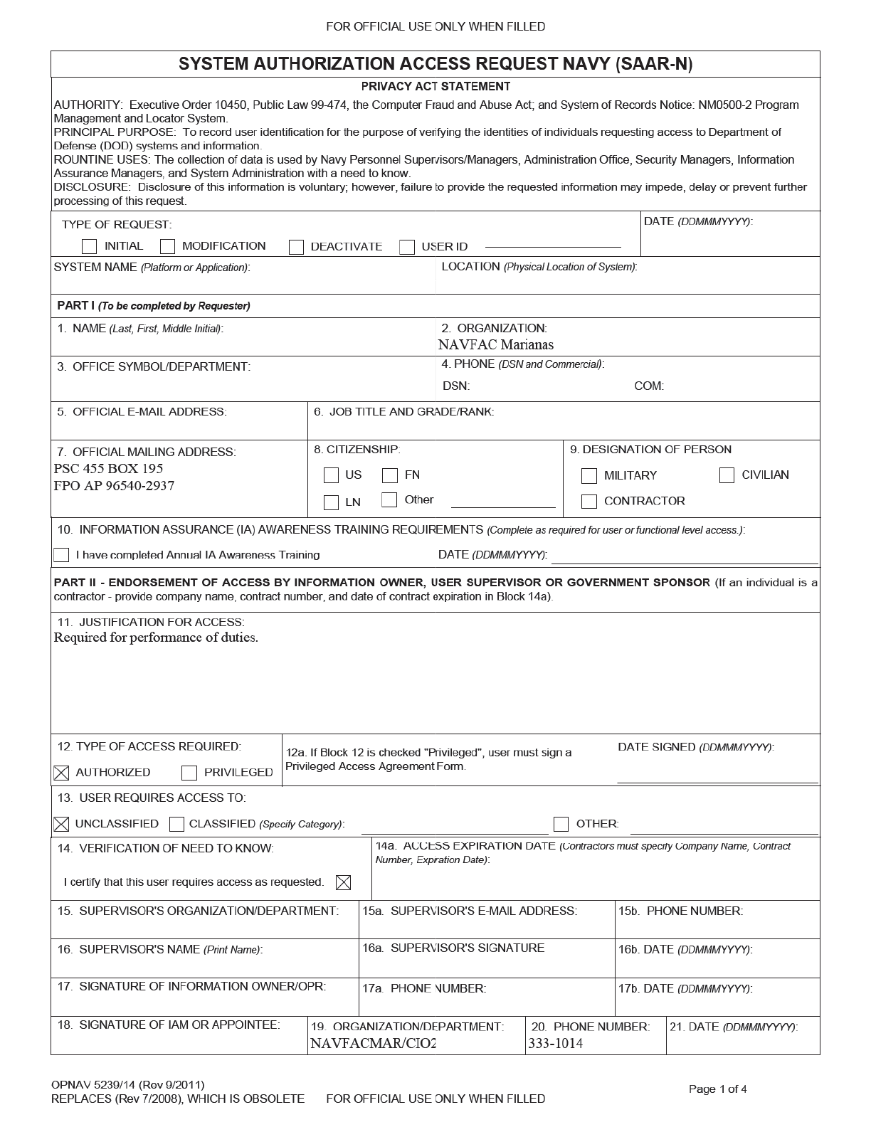

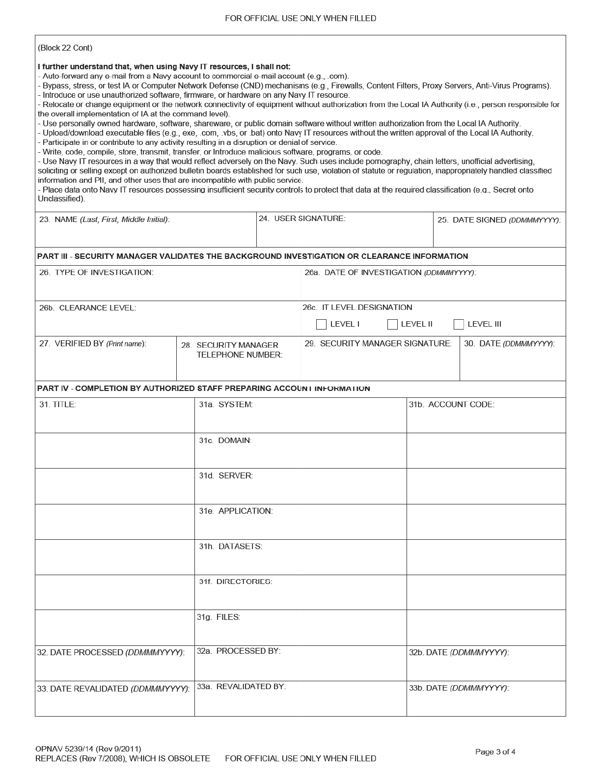
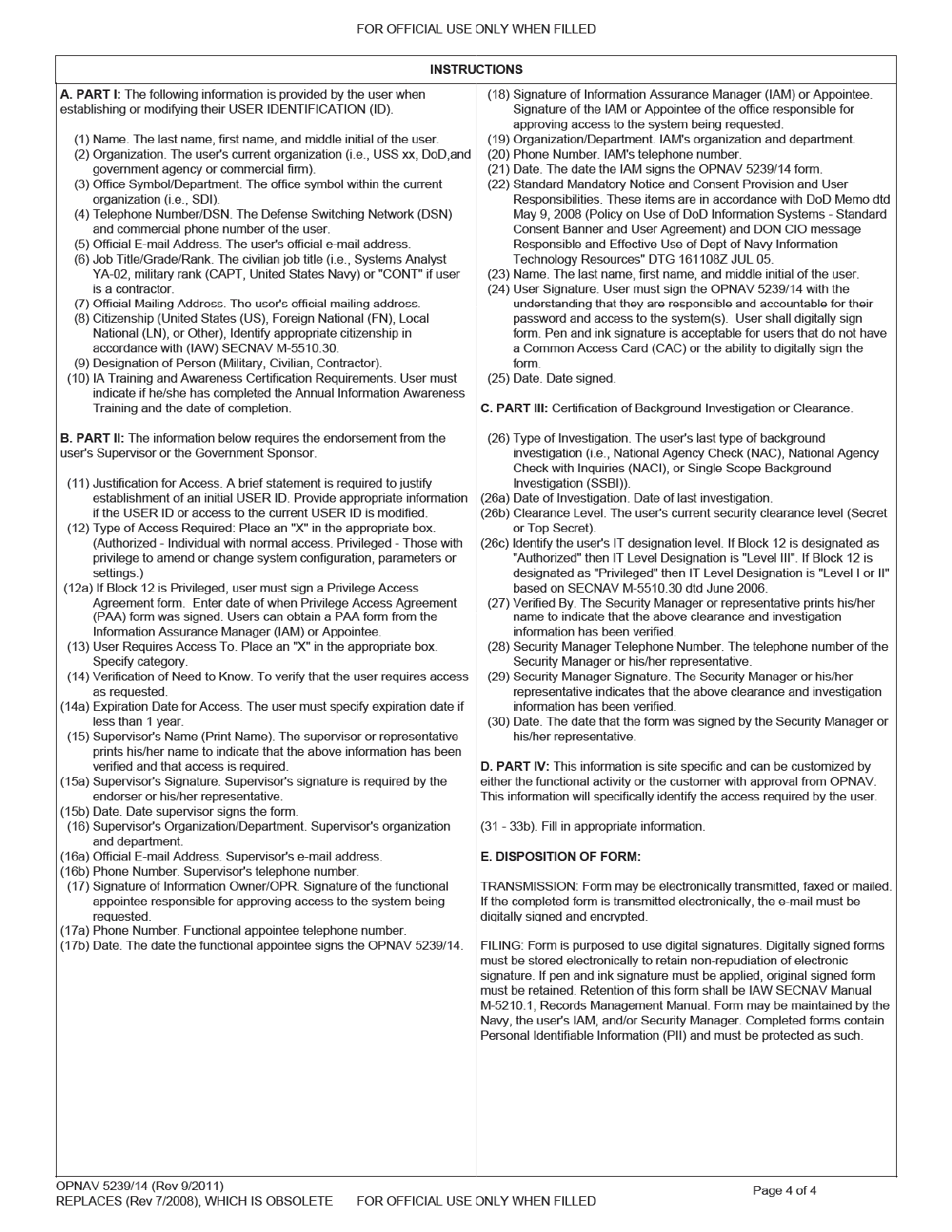
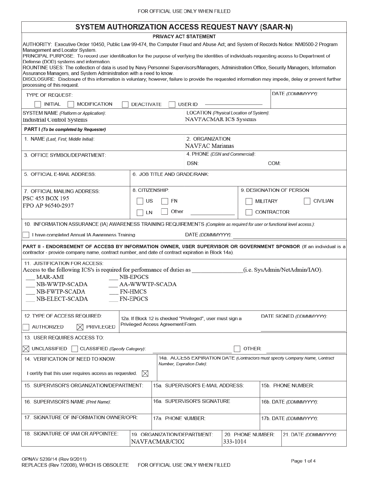
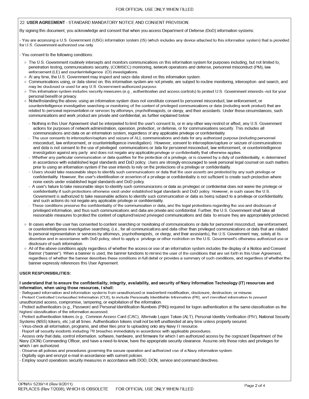


NAVFAC MARIANAS ICS IA Addendum
In addition to the mandated annual DoD Information Assurance training, the following
requirements will apply to all NAVFAC Marianas Industrial Control Systems (ICS) Users.
1. The use of USB thumb drives, memory sticks and camera flash memory is prohibited from
being connected to any NAVFAC Marianas ICS system.
2. Non-government computers are prohibited from being connected to the NAVFAC Marianas
ICS network.
3. Only approved users will log in to an ICS system with credentials provided by NAVFAC
Marianas CIO.
4. User account and passwords will NOT be shared.
5. Government ICS laptops/computers will NOT be moved between government installations
and/or systems without prior approval.
6. Government ICS laptops/computers will NOT be connected to any other network except for
NAVFAC Marianas ICS.
7. Government ICS laptops/computers will NOT be connected to the internet.
8. Government ICS laptops/computers will NOT be modified without written consent of
NAVFAC Marianas CIO. This includes installation of software.
9. Control Systems security measures will NOT be bypassed or deactivated.
Note: Violation of this agreement will result in user account being deactivated and possible
disciplinary actions.
__________________________________
User Printed Name
__________________________________ _____________________
User Signature Date

INFORMATION SYSTEM (IS) PRIVILEGED ACCESS AGREEMENT AND
ACKNOWLEDGMENT (PAA) OF RESPONSIBILITIES
Page 1 of 3
SECNAV M-5239.2
SECNAV 5239/1 (Apr 2016)
Request Date:
PRIVACY ACT STATEMENT
AUTHORITY FOR MAINTENANCE OF THE SYSTEM:
10 U.S.C. 5013, Secretary of the Navy; 10 U.S.C. 5041, Headquarters, Marine Corps; and E.O. 9397 (SSN).
PURPOSE(S):
To manage, supervise, and administer programs for all Department of the Navy civilian, military, and contractor personnel. Information is used to prepare organizational locator,
recall rosters, and social rosters; notify personnel of arrival of visitors; locate individuals on routine and/or emergency matters; locate individuals during medical emergencies,
facility evacuations and similar threat situations; provide mail distribution and forwarding addresses; compile a social roster for official and non-official functions; send personal
greetings and invitations; track attendance at training; identify routine and special work assignments; determine clearance for access control; identify record handlers of hazardous
materials; record rental of welfare and recreational equipment; track beneficial suggestions and awards; control the budget; travel claims; track manpower, grades, and personnel
actions; maintain statistics for minorities; track employment; track labor costing; prepare watch bills; project retirement losses; verify employment to requesting banking
activities; rental and credit organizations; name change location; checklist prior to leaving activity; safety reporting/monitoring; and, similar administrative uses requiring
personnel data.
ROUTINE USES:
In addition to those disclosures generally permitted under 5 U.S.C. 552a(b) of the Privacy Act of 1974, these records contained therein may specifically be disclosed outside the
DoD as a routine use pursuant to 5 U.S.C. 552a(b)(3) as follows: To arbitrators and hearing examiners for use in civilian personnel matters relating to civilian grievances and
appeals. To authenticate authorization for access to services and spaces such as Morale, Welfare, and Recreation (MWR) facilities and food services. The DoD 'Blanket Routine
Uses' that appear at the beginning of the Navy's compilation of systems of records notices apply to this system.
DISCLOSURE: Disclosure of this information is voluntary; however, failure to provide the requested information will result in denial of privileged access to the requested
information system..
SYSTEM OF RECORDS NOTICE: http://dpcld.defense.gov/Privacy/SORNsIndex/DODwideSORNArticleView/tabid/6797/Article/570436/nm05000-2.aspx
PART I PRIVILEDGED USER INFORMATION
1. Name: (Last First Middle Initial): 2. Official Telephone Number: 3. Official Email Address:
4. Organization & Office Symbol/Department:
5. DoD/Component Information System Owner:
DoD/Components
*NOTE: DoD Component collectively refers to: OSD, the Military Departments, the Office of the Chairman of the Joint Chiefs of Staff and the Joint Staff, the Combatant
Commands, the Office of the Inspector General of the Department of Defense, the Defense Agencies, the DoD Field Activities, and all other organizational entities in the DoD.
6. Information System (IS) Full Name: 7. Information System (IS) Acronym:
8. Information System (IS) Details: (Brief Description (optional))
PART II PRIVILEGED ACCESS AGREEMENT
1. I understand there are two DoD Information Systems (IS), classified (SIPRNET) and unclassified (NIPRNET), and that I have
the necessary clearance for privileged access to the IS. I will not introduce or process data or software
for the IS that I have not been specifically authorized to handle.
2. I understand the need to protect all passwords and other authenticators at the highest level of data they secure. I will not
share any password(s), account(s), or other authenticators with other coworkers or other personnel not authorized to access
the IS. As a privileged user, I understand the need to protect the root password and/or authenticators at the
highest level of data it secures. I will NOT share the root password and/or authenticators with coworkers who are not
authorized IS access.
3. I understand that I am responsible for all actions taken under my account(s), root, or otherwise. I will not attempt to
“hack” the network or any connected information systems, or gain access to data to which I do not have authorized access.
4. I understand my responsibility to appropriately protect and label all output generated under my account (including printed
materials, magnetic tapes, floppy disks, and downloaded hard disk files).
5. I will immediately report any indication of computer network intrusion, unexplained degradation or interruption of
network services, or the actual or possible compromise of data or file access controls to the appropriate
Information System Security Manager (ISSM). I will NOT install, modify, or remove any hardware or software (e.g.,
freeware/shareware and security tools) without written permission and approval from the ISSM or senior
representatives.
6. I will not install any unauthorized software (e.g., games, entertainment software) or hardware (e.g., sniffers).

INFORMATION SYSTEM (IS) PRIVILEGED ACCESS AGREEMENT AND
ACKNOWLEDGMENT (PAA) OF RESPONSIBILITIES
Page 2 of 3
SECNAV M-5239.2
SECNAV 5239/1 (Apr 2016)
Request Date:
7. I will not add/remove any users' names to the Domain Administrators, Local Administrator, or Power Users group without
the prior approval and direction of the ISSM or senior representatives.
8. I will not introduce any unauthorized code, Trojan horse programs, malicious code, or viruses into the local
area networks.
9. I understand that I am prohibited from the following while using the DoD IS:
a. Introducing Classified and/or Controlled Unclassified Information (CUI) into a NIPRNET environment.
b. Accessing, storing, processing, displaying, distributing, transmitting, or viewing material that is abusive, harassing,
defamatory, vulgar, pornographic, profane, or racist; that promotes hate crimes, or is subversive or objectionable by
nature, including material encouraging criminal activity, or violation of local, state, federal, national, or international law.
c. Storing, accessing, processing, or distributing Classified, Proprietary, CUI, For Official Use Only (FOUO), or Privacy
Act protected information in violation of established security and information release policies.
d. Obtaining, installing, copying, pasting, transferring, or using software or other materials obtained in violation of the
appropriate vendor's patent, copyright, trade secret, or license agreement.
e. Knowingly writing, coding, compiling, storing, transmitting, or transferring malicious software code, to include
viruses, logic bombs, worms, and macro viruses.
f. Engaging in prohibited political activity.
g. Using the system for personal financial gain such as advertising or solicitation of services or sale of personal property
(e.g., eBay), or stock trading (i.e., issuing buy, hold, and/or sell directions to an online broker).
h. Fundraising activities, either for profit or non-profit, unless the activity is specifically approved by the organization
(e.g., organization social event fund raisers and charitable fund raisers, without approval).
i. Gambling, wagering, or placing of any bets.
j. Writing, forwarding, or participating in chain letters.
k. Posting personal home pages.
l. Any other actions prohibited by DoD Directive 5500.7-R or any other DoD issuances.
10. Personal encryption of electronic communications is strictly prohibited and can result in the immediate termination of access.
11. I understand that if I am in doubt as to any of my roles or responsibilities I will contact the ISSM or Cyber
IT/CSWF-PM for clarification.
12. I understand that all information processed on the is subject to monitoring. This includes email and
browsing the web.
13. I will not allow any user who is not cleared access to the network or any other connected system without prior approval or
specific guidance from the ISSM.
14. I will use the special access or privileges granted to me ONLY to perform authorized tasks or mission related functions.
15. I will not use any DoD/Components IS to violate software copyright by making illegal copies of software.
16. I will ONLY use my PRIVILEGED USER account for official administrative actions. This account will NOT be used for
day to day network communications.
17. I will obtain and maintain required qualification(s), according to SECNAV M-5239 and maintain certification(s) (if
applicable) according to the certification provider, to retain privileged system access.
18. I understand that failure to comply with the above requirements will be reported and may result in the following actions:
a. Revocation of IS privileged access.
b. Counseling.
c. Adverse actions pursuant to the Uniform Code of Military Justice and/or criminal prosecution.
d. Disciplinary action, discharge or loss of employment.
e. Revocation of Security Clearance.

INFORMATION SYSTEM (IS) PRIVILEGED ACCESS AGREEMENT AND
ACKNOWLEDGMENT (PAA) OF RESPONSIBILITIES
Page 3 of 3
SECNAV M-5239.2
SECNAV 5239/1 (Apr 2016)
Request Date:
26. Command Cyber IT/CSWF-PM Signature:
9. Privileged User Name:
14. Privileged User Signature:13. Date signed:
15. Command ISSM Name:
19. Date signed: 20. Command ISSM Signature:
21. Command Cyber IT/CSWF-PM:
25. Date signed:
PART III CERTIFICATION OF DOD COMPONENT OPR AND/OR ACTION OFFICER, APPROVING OFFICIAL
PRIVILEGED USER CERTIFICATION OF INFORMATION
COMMAND ISSM APPROVAL
COMMAND CYBER IT/CSWF-PM APPROVAL
12. Organization & Office Symbol/Department:
10. Official Email Address: 11. Official Phone Number:
18. Organization & Office Symbol/Department:
16. Official Email Address: 17. Official Phone Number:
24. Organization & Office Symbol/Department:
22. Official Email Address: 23. Official Phone Number:
Page intentionally left blank

NAVFACMAR PWUC
15 November 2018
This PWUC supersedes: PWUC dated 14July2011; Revision 1 dated 02April2015
Appendix 7
FORM –
INFORMATION SYSTEM (IS) PRIVILEGED ACCESS AGREEMENT
& ACKNOWLEDGEMENT (PAA) OF RESPONSIBILITIES
INFORMATION SYSTEM (IS) PRIVILEGED ACCESS AGREEMENT AND
ACKNOWLEDGMENT (PAA) OF RESPONSIBILITIES
Page 1 of 3
SECNAV M-5239.2
SECNAV 5239/1 (Apr 2016)
Request Date:
PRIVACY ACT STATEMENT
AUTHORITY FOR MAINTENANCE OF THE SYSTEM:
10 U.S.C. 5013, Secretary of the Navy; 10 U.S.C. 5041, Headquarters, Marine Corps; and E.O. 9397 (SSN).
PURPOSE(S):
To manage, supervise, and administer programs for all Department of the Navy civilian, military, and contractor personnel. Information is used to prepare organizational locator,
recall rosters, and social rosters; notify personnel of arrival of visitors; locate individuals on routine and/or emergency matters; locate individuals during medical emergencies,
facility evacuations and similar threat situations; provide mail distribution and forwarding addresses; compile a social roster for official and non-official functions; send personal
greetings and invitations; track attendance at training; identify routine and special work assignments; determine clearance for access control; identify record handlers of hazardous
materials; record rental of welfare and recreational equipment; track beneficial suggestions and awards; control the budget; travel claims; track manpower, grades, and personnel
actions; maintain statistics for minorities; track employment; track labor costing; prepare watch bills; project retirement losses; verify employment to requesting banking
activities; rental and credit organizations; name change location; checklist prior to leaving activity; safety reporting/monitoring; and, similar administrative uses requiring
personnel data.
ROUTINE USES:
In addition to those disclosures generally permitted under 5 U.S.C. 552a(b) of the Privacy Act of 1974, these records contained therein may specifically be disclosed outside the
DoD as a routine use pursuant to 5 U.S.C. 552a(b)(3) as follows: To arbitrators and hearing examiners for use in civilian personnel matters relating to civilian grievances and
appeals. To authenticate authorization for access to services and spaces such as Morale, Welfare, and Recreation (MWR) facilities and food services. The DoD 'Blanket Routine
Uses' that appear at the beginning of the Navy's compilation of systems of records notices apply to this system.
DISCLOSURE: Disclosure of this information is voluntary; however, failure to provide the requested information will result in denial of privileged access to the requested
information system..
SYSTEM OF RECORDS NOTICE: http://dpcld.defense.gov/Privacy/SORNsIndex/DODwideSORNArticleView/tabid/6797/Article/570436/nm05000-2.aspx
PART I PRIVILEDGED USER INFORMATION
1. Name: (Last First Middle Initial): 2. Official Telephone Number: 3. Official Email Address:
4. Organization & Office Symbol/Department:
5. DoD/Component Information System Owner:
DoD/Components
*NOTE: DoD Component collectively refers to: OSD, the Military Departments, the Office of the Chairman of the Joint Chiefs of Staff and the Joint Staff, the Combatant
Commands, the Office of the Inspector General of the Department of Defense, the Defense Agencies, the DoD Field Activities, and all other organizational entities in the DoD.
6. Information System (IS) Full Name: 7. Information System (IS) Acronym:
8. Information System (IS) Details: (Brief Description (optional))
PART II PRIVILEGED ACCESS AGREEMENT
1. I understand there are two DoD Information Systems (IS), classified (SIPRNET) and unclassified (NIPRNET), and that I have
the necessary clearance for privileged access to the IS. I will not introduce or process data or software
for the IS that I have not been specifically authorized to handle.
2. I understand the need to protect all passwords and other authenticators at the highest level of data they secure. I will not
share any password(s), account(s), or other authenticators with other coworkers or other personnel not authorized to access
the IS. As a privileged user, I understand the need to protect the root password and/or authenticators at the
highest level of data it secures. I will NOT share the root password and/or authenticators with coworkers who are not
authorized IS access.
3. I understand that I am responsible for all actions taken under my account(s), root, or otherwise. I will not attempt to
“hack” the network or any connected information systems, or gain access to data to which I do not have authorized access.
4. I understand my responsibility to appropriately protect and label all output generated under my account (including printed
materials, magnetic tapes, floppy disks, and downloaded hard disk files).
5. I will immediately report any indication of computer network intrusion, unexplained degradation or interruption of
network services, or the actual or possible compromise of data or file access controls to the appropriate
Information System Security Manager (ISSM). I will NOT install, modify, or remove any hardware or software (e.g.,
freeware/shareware and security tools) without written permission and approval from the ISSM or senior
representatives.
6. I will not install any unauthorized software (e.g., games, entertainment software) or hardware (e.g., sniffers).

INFORMATION SYSTEM (IS) PRIVILEGED ACCESS AGREEMENT AND
ACKNOWLEDGMENT (PAA) OF RESPONSIBILITIES
Page 2 of 3
SECNAV M-5239.2
SECNAV 5239/1 (Apr 2016)
Request Date:
7. I will not add/remove any users' names to the Domain Administrators, Local Administrator, or Power Users group without
the prior approval and direction of the ISSM or senior representatives.
8. I will not introduce any unauthorized code, Trojan horse programs, malicious code, or viruses into the local
area networks.
9. I understand that I am prohibited from the following while using the DoD IS:
a. Introducing Classified and/or Controlled Unclassified Information (CUI) into a NIPRNET environment.
b. Accessing, storing, processing, displaying, distributing, transmitting, or viewing material that is abusive, harassing,
defamatory, vulgar, pornographic, profane, or racist; that promotes hate crimes, or is subversive or objectionable by
nature, including material encouraging criminal activity, or violation of local, state, federal, national, or international law.
c. Storing, accessing, processing, or distributing Classified, Proprietary, CUI, For Official Use Only (FOUO), or Privacy
Act protected information in violation of established security and information release policies.
d. Obtaining, installing, copying, pasting, transferring, or using software or other materials obtained in violation of the
appropriate vendor's patent, copyright, trade secret, or license agreement.
e. Knowingly writing, coding, compiling, storing, transmitting, or transferring malicious software code, to include
viruses, logic bombs, worms, and macro viruses.
f. Engaging in prohibited political activity.
g. Using the system for personal financial gain such as advertising or solicitation of services or sale of personal property
(e.g., eBay), or stock trading (i.e., issuing buy, hold, and/or sell directions to an online broker).
h. Fundraising activities, either for profit or non-profit, unless the activity is specifically approved by the organization
(e.g., organization social event fund raisers and charitable fund raisers, without approval).
i. Gambling, wagering, or placing of any bets.
j. Writing, forwarding, or participating in chain letters.
k. Posting personal home pages.
l. Any other actions prohibited by DoD Directive 5500.7-R or any other DoD issuances.
10. Personal encryption of electronic communications is strictly prohibited and can result in the immediate termination of access.
11. I understand that if I am in doubt as to any of my roles or responsibilities I will contact the ISSM or Cyber
IT/CSWF-PM for clarification.
12. I understand that all information processed on the is subject to monitoring. This includes email and
browsing the web.
13. I will not allow any user who is not cleared access to the network or any other connected system without prior approval or
specific guidance from the ISSM.
14. I will use the special access or privileges granted to me ONLY to perform authorized tasks or mission related functions.
15. I will not use any DoD/Components IS to violate software copyright by making illegal copies of software.
16. I will ONLY use my PRIVILEGED USER account for official administrative actions. This account will NOT be used for
day to day network communications.
17. I will obtain and maintain required qualification(s), according to SECNAV M-5239 and maintain certification(s) (if
applicable) according to the certification provider, to retain privileged system access.
18. I understand that failure to comply with the above requirements will be reported and may result in the following actions:
a. Revocation of IS privileged access.
b. Counseling.
c. Adverse actions pursuant to the Uniform Code of Military Justice and/or criminal prosecution.
d. Disciplinary action, discharge or loss of employment.
e. Revocation of Security Clearance.
INFORMATION SYSTEM (IS) PRIVILEGED ACCESS AGREEMENT AND
ACKNOWLEDGMENT (PAA) OF RESPONSIBILITIES
Page 3 of 3
SECNAV M-5239.2
SECNAV 5239/1 (Apr 2016)
Request Date:
26. Command Cyber IT/CSWF-PM Signature:
9. Privileged User Name:
14. Privileged User Signature:13. Date signed:
15. Command ISSM Name:
19. Date signed: 20. Command ISSM Signature:
21. Command Cyber IT/CSWF-PM:
25. Date signed:
PART III CERTIFICATION OF DOD COMPONENT OPR AND/OR ACTION OFFICER, APPROVING OFFICIAL
PRIVILEGED USER CERTIFICATION OF INFORMATION
COMMAND ISSM APPROVAL
COMMAND CYBER IT/CSWF-PM APPROVAL
12. Organization & Office Symbol/Department:
10. Official Email Address: 11. Official Phone Number:
18. Organization & Office Symbol/Department:
16. Official Email Address: 17. Official Phone Number:
24. Organization & Office Symbol/Department:
22. Official Email Address: 23. Official Phone Number:
