Quick Start Guide
Cisco 250 Series Smart Switches

2 Cisco 250 Series Smart Switches
Welcome
Thank you for choosing the Cisco 250 Series Smart Switch. These
switches are designed to be operational right out-of-the-box as a standard
switch. In the default configuration, it forwards packets between the
connecting devices after powered up.
Package Contents
• Cisco 250 Series Smart Switch
• Rackmount Kit
• Power Cord or Adapter
• This Quick Start Guide
• Pointer Card with China RoHS
• Technical Support Contacts
• EU Directives 1999/5/EC Compliance Information (for EU SKU only)
This guide familiarizes you with the smart switch layout and describes how
to deploy the switch in your network. For additional information, see
www.cisco.com/go/250switches
Before You Begin
Before you begin the installation, make sure that you have the following:
• RJ-45 Ethernet cables (Category 5e or higher) for connecting network
devices.
• Tools for installing the hardware. The rack-mount kit packed with the
switch contains four rubber feet for desktop placement, and two
brackets and twelve screws for rack-mounting. If the supplied screws
are lost, use replacement screws in the following size:
– Diameter of the screw head: 6.9 mm
– Length of face of screw head to base of screw: 5.9 mm
– Shaft diameter: 3.94 mm
• The wall mount kit includes screws and anchors. If the supplied screws
are lost, use replacement screws in the following size:
– Diameter of the screw head: 6.8 mm
– Length of face of screw head to base of screw: 16 mm
– Shaft diameter: 3.5 x 1.3 mm
1

Cisco 250 Series Smart Switches 3
• Computer with Internet Explorer (version 9.0, 10.0, 11.0), or Firefox
(version 36.0, 37.0, or higher), or Chrome (version 40,41,42 or higher) for
using the web-based interface.
Mounting the Cisco 250 Series Smart
Switches
There are three ways to install the switch:
• Place the switch on a flat surface. To place the switch on a desktop,
install the four rubber feet (included) on the bottom of the switch.
• Mount the switch in a standard rack (1 rack unit high).
• Mount on a wall.
Placement Tips
Do not mount the device in a location where any of the following conditions
exist:
• High Ambient Temperature—To prevent the switch from overheating,
do not operate it in an area that exceeds an ambient temperature of
122°F (50°C).
•Air Flow—Both side panels must be unobstructed to prevent
overheating.
•Overloading—The device must be level, stable, and secure to prevent
it from sliding or shifting out-of-position.
• Circuit Overloading—Adding the device to the power outlet must not
overload that circuit.
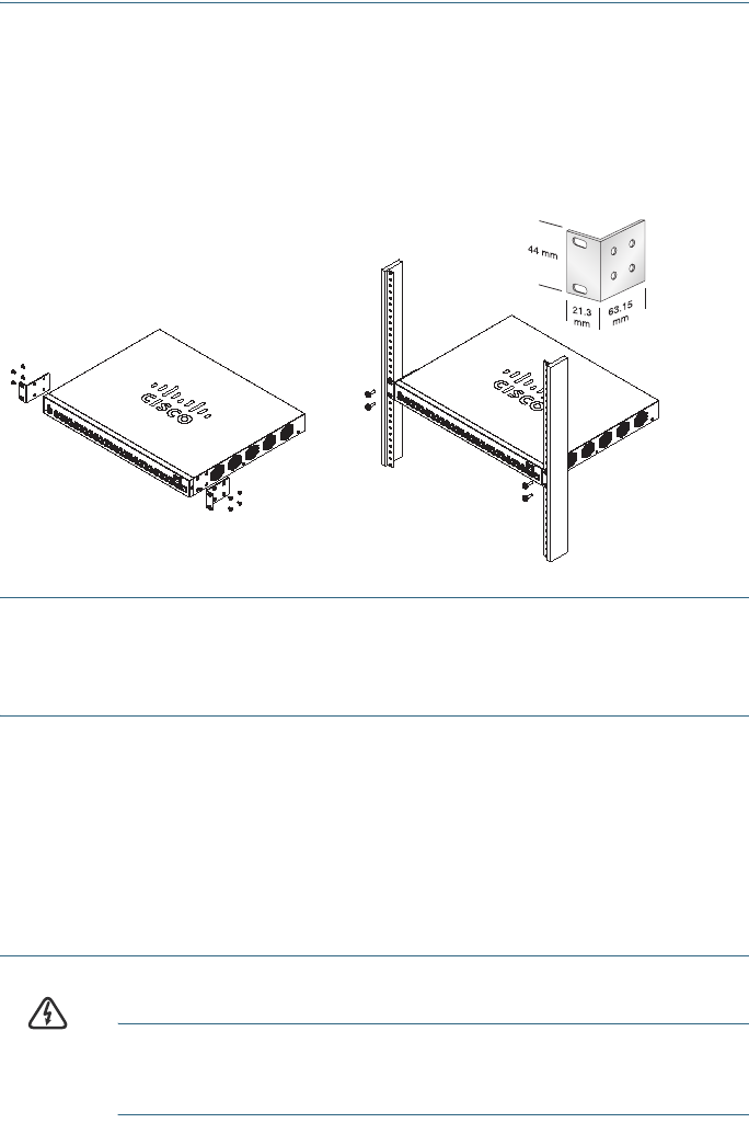
Rack Mounting
You can mount the switches in any standard size, 19-inch (about 48 cm)
wide rack. The switch requires 1 rack unit (RU) of space, which is 1.75
inches (44.45 mm) high.
CAUTION For stability, load the rack from the bottom to the top, with the
heaviest devices on the bottom. A top-heavy rack is likely to
be unstable and might tip over.
2
4 Cisco 250 Series Smart Switches
To install the switch into a 19-inch standard chassis:
STEP 1 Place one of the supplied brackets on the side of the switch so that
the four holes of the brackets align to the screw holes, and then use
the four supplied screws to secure it.
STEP 2 Repeat the previous step to attach the other bracket to the opposite
side of the switch.
STEP 3 After the brackets are securely attached, the switch is now ready to
be installed into a standard 19-inch rack.
Wall Mounting
To mount the Cisco 250 Series Smart Switches to a wall:
STEP 1 Determine where you want to mount the device. Verify that the
surface is smooth, flat, dry, and sturdy.
STEP 2 Drill two pilot holes into the surface of the wall 94 mm apart.
STEP 3 Insert a screw into each hole, leaving a gap between the surface
and the base of the screw head.
STEP 4 Place the bottom of the switch over the screws and slide the
switch down until the screws fit snugly into the slots.
WARNING Insecure mounting may damage the device or cause injury.
Cisco is not responsible for damages incurred by insecure wall
or ceiling mounting.
400925
Cisco 250 Series Smart Switches 5
Connecting Network Devices
To connect the smart switch to the network:
STEP 1 Connect the Ethernet cable to the Ethernet port of a computer,
printer, network storage, or other network device.
STEP 2 Connect the other end of the Ethernet cable to one of the
numbered smart switch Ethernet ports.
The LED of the port lights if the device connected is active. Refer to
Features of the Cisco 250 Series Smart Switches for details
about the different ports and LEDs on each switch.
STEP 3 Repeat Step 1 and Step 2 for each device you want to connect to
the smart switch.
NOTE Cisco strongly recommends using Cat5 or better cable for Gigabit
connectivity. When you connect your network devices, do not exceed
the maximum cabling distance of 100 meters (328 feet). It can take up to
one minute for the attached devices or the LAN to be operational after it
is connected. This is normal behavior.
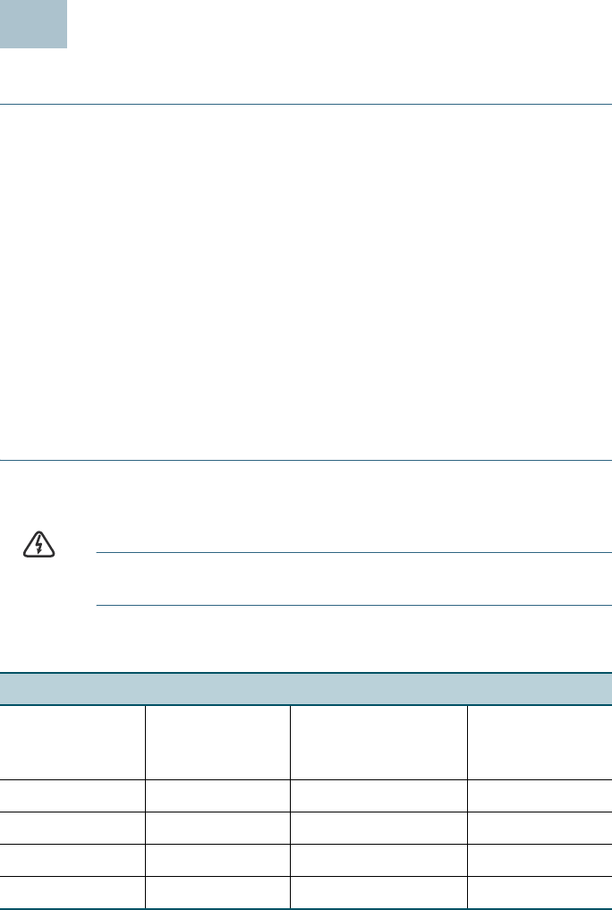
Power over Ethernet Considerations
WARNING The switch is to be connected only to PoE networks without
routing to the outside plant.
If your switch is one of the Power over Ethernet (PoE) models, consider the
following power requirement:
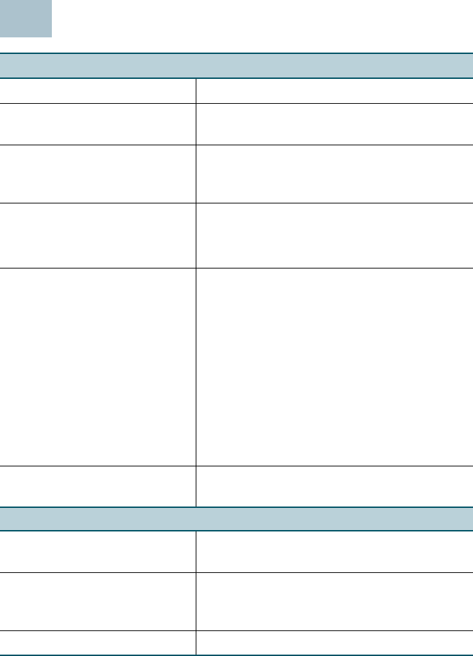
250 Series Switches with Power Over Ethernet
Model Power
Dedicated to
PoE
Number of Ports
Supporting PoE
PoE Standard
Supported
SF250-48HP 195 Watts 1—48 802.3af/at
SG250-10P 62 Watts 1—8 802.3af/at
SG250-26HP 100 Watts 1—24 802.3af/at
SG250-26P 195 Watts 1—24 802.3af/at
3

6 Cisco 250 Series Smart Switches
CAUTION Consider the following when connecting switches capable of
supplying PoE:
The PoE models of the switches are PSE (Power Sourcing
Equipment) that are capable of supplying DC power to
attaching PD (Powered Devices). These devices include VoIP
phones, IP cameras, and wireless access points. The PoE
switches can detect and supply power to pre-standard
legacy PoE Powered Devices. Due to the support of legacy
PoE, it is possible that a PoE switch acting as a PSE may
mistakenly detect and supply power to an attaching PSE,
including other PoE switches, as a legacy PD.
Even though PoE switches are PSE, and as such should be
powered by AC, they could be powered up as a legacy PD
by another PSE due to false detection. When this happens,
the PoE switch may not operate properly and may not be
able to properly supply power to its attaching PDs.
To prevent false detection, you should disable PoE on the
ports on the PoE switches that are used to connect to PSEs.
You should also first power up a PSE device before
connecting it to a PoE switch. When a device is being falsely
detected as a PD, you should disconnect the device from the
PoE port and power recycle the device with AC power
before reconnecting its PoE ports.

Cisco 250 Series Smart Switches 7
Configuring the Cisco 250 Series Smart
Switches
Before You Begin
Verify the managing computer requirements in the product release notes.
Configuring Your Switch Using the Web-based Interface
To access the switch by using the web-based interface, you must know
the IP address the switch is using. The switch uses the factory default IP
address of 192.168.1.254, with a subnet of /24.
When the switch is using the factory default IP address, the System LED
flashes continuously. When the switch is using a DHCP server-assigned IP
address or an administrator has configured a static IP address, the System
LED is a steady green (DHCP is enabled by default).
NOTE If you are managing the switch through a network connection and
the switch IP address is changed, either by a DHCP server or manually,
your access to the switch will be lost. You must enter the new IP address
the switch is using into your browser to use the web-based interface.
To configure the smart switch:
STEP 1 Power on the computer and the switch.
STEP 2 Connect the computer to any network port on the front panel of the
switch.
STEP 3 Set up the IP configuration on your computer.
a. If the switch is using the factory default IP address of
192.168.1.254/24, you must chose an IP address for the
computer in the range of 192.168.1.2—192.168.1.253 that is not
already in use.
b. If the IP addresses is assigned by a DHCP server, make sure
the DHCP server is running and can be reached from the
switch and the computer. It might be necessary to disconnect
and reconnect the devices for them to discover their new IP
addresses from the DHCP server.
NOTE Details on how to change the IP address on your computer
depend upon the type of architecture and operating system you are
using. Use the computer Help and Support functionality to search
for “IP Addressing.”
454
8 Cisco 250 Series Smart Switches
S
TEP 4 Open a Web browser window. If you are prompted to install an
ActiveX plug-in when connecting to the device, follow the prompts
to accept the plug-in.
STEP 5 Enter the switch IP address in the address bar and press Enter. For
example, http://192.168.1.254.
The Switch Login Page
displays.
STEP 6 Enter the default login information:
• Username is cisco
• Default password is cisco (passwords are case sensitive)
STEP 7 Click Log In.
If this is the first time that you have logged on with the default
username and password, the Change Password page opens. The
rules for constructing a new password are displayed on the page.
STEP 8 Enter a new password and confirm the password.
NOTE Password complexity is enabled by default. The password
must comply with the default complexity rules or it can be disabled
temporarily by checking Disable next to the Password Strength
Enforcement option.
STEP 9 Click Apply.
CAUTION Make sure that any configuration changes made are saved
before exiting from the web-based interface by clicking on
the Save icon. Exiting before you save your configuration will
result in all changes being lost.
The Getting Started window displays. You are now ready to configure the
switch. Refer to your Administration Guide for further information.

Cisco 250 Series Smart Switches 9
Troubleshoot Your Connection
If you cannot access your switch from the web-based interface, the switch
may not be reachable from your computer. You can test network
connections by using ping on a computer running Windows:
STEP 1 Open a command window by using Start > Run and enter cmd.
STEP 2 At the Command window prompt enter ping and the smart switch
IP address. For example ping 192.168.1.254 (the default IP
address of the smart switch).
If you can reach the switch, you should get a reply similar to the
following:
Pinging 192.168.1.254 with 32 bytes of data:
Reply from 192.168.1.254: bytes=32 time<1ms TTL=128
If you cannot reach the switch, you should get a reply similar to the
following:
Pinging 192.168.1.254 with 32 bytes of data:
Request timed out.
10 Cisco 250 Series Smart Switches
Possible Causes and Resolutions
The Switch is not Powering on
• Verify the power cord is plugged firmly into the switch and into the
power outlet.
• Verify that the power outlet is active.
• Verify that the computer is on.
• Replace the power adapter, before replacing the switch, if the situation
continues.
Bad Ethernet connection
• Check the LEDs for proper indications.
• Check the connectors of the Ethernet cable to ensure that they are
firmly plugged into the switch and your computer.
• Use a different Ethernet cable or port.
IP Addressing Issues
• The Cisco switches can also be accessed by the Cisco FindIT Network
Discovery Utility that automatically discovers all Cisco Small
Business devices in the same local network segment as your computer.
You can view device information including the current IP address,
download the latest firmware for the device, or launch the product
configuration utility to view and configure the settings. For more
information, see www.cisco.com/go/findit.
• Verify that you are using the correct IP address of the switch. The
System LED provides an indication of where the switch received the IP
address.
• Make sure that no other device is using the same IP address as the
switch.
No IP route
If the switch and your computer are in different IP subnets, you need
one or more routers to route the packets between the two subnets.
Unusually long access time
Due to the standard spanning tree loop detection logic, adding new
connections may take 30 to 60 seconds for the affected interfaces
and/or LAN to become operational.

Cisco 250 Series Smart Switches 11
Features of the Cisco 250 Series Smart
Switches
This section describes the exterior of the smart switches including ports,
LEDs, and connections. Not all models have all of the features described.
Ports
USB Port—The USB port connects the switch to a USB device so that you
can save and restore the configuration files, firmware images, and
SYSLOG files through the connected USB device.
RJ-45 Ethernet Ports—Use these ports to connect network devices, such
as computers, printers, and access points, to the switch.
SFP (if present)—The small form-factor pluggable (SFP) ports are
connection points for modules, so the switch can link to other switches.
These ports are also commonly referred to as miniGigaBit Interface
Converter (miniGBIC) ports. The term SFP is used in this guide.
• SFP ports are compatible with Cisco modules MGBT1, MGBSX1,
MGBLH1, MGBLX1, MGBBX1, MFELX1, MFEFX1, and MFEBX1, as well as
other brands of modules.
• Some SFP interfaces are shared with one other RJ-45 port, called a
combo port. When the SFP is active, the adjacent RJ-45 port is
disabled.
• The LEDs of the corresponding RJ-45 port flash green to respond to the
SFP interface traffic.
LEDs
System LED—(Green) The LED lights steady when the switch is powered
on, and flashes when booting, performing self tests, and acquiring an IP
address. If the LED flashes amber, the switch has detected a hardware
failure.
LINK/ACT LED—(Green) Located on the left of the port. The LED lights
steady when a link between the corresponding port and another device is
detected, and flashes when the port is passing traffic.
NOTE The System and LINK/ACT LEDs are on each model of the switch.
The following LEDs are only present on switch models that have those
capabilities:
PoE (if present)—(Amber) Located on the right of the port. The LED lights
steady to indicate that power is being supplied to a device attached to the
corresponding port.
5
12 Cisco 250 Series Smart Switches
100M LED (if present)—(Green) Located on the right of the port. The LED
lights steady when another device is connected to the port, is powered on,
and a 100 Mbps link is established between the devices. When the LED is
off, the connection speed is under 100 Mbps or nothing is cabled to the
port.
Gigabit LED (if present)—(Green) Located on the right of the port. The LED
lights steady when another device is connected to the port, is powered on,
and a 1000 Mbps link is established between the devices. When the LED is
off, the connection speed is under 1000 Mbps or nothing is cabled to the
port.
SFP (if present)—(Green) Located on the right of a GE port. The LED lights
steady when a connection is made through the shared port, and flashes
when the port is passing traffic.
Additional Features
The switch might also have a reset button. The switch can be reset by
inserting a pin or paper clip into the reset opening. See Returning the
Switch to the Factory Default Settings for details.
Back Panel
The power port is located on the back panel of the smart switch.
Cisco 250 Series Smart Switches 13
Returning the Switch to the Factory
Default Settings
To use the Reset button to reboot or reset the smart switch, do the
following:
• To reboot the smart switch, press the Reset button for less than 10
seconds.
• To restore the smart switch configuration to the factory default settings:
1. Disconnect the smart switch from the network or disable all DHCP
servers on your network.
2. With the power on, press and hold the Reset button for more than
10 seconds.
WARNING This is a class A product. In a domestic environment this
product may cause radio interference in which case the user
may be required to take adequate measures.
6
14 Cisco 250 Series Smart Switches
Where to Go From Here
Support
Cisco Support Community www.cisco.com/go/smallbizsupport
Cisco Support and
Resources
www.cisco.com/go/smallbizhelp
Phone Support Contacts www.cisco.com/en/US/support/
tsd_cisco_small_business
_support_center_contacts.html
Cisco Firmware Downloads www.cisco.com/go/smallbizfirmware
Select a link to download firmware for
Cisco Products. No login is required.
Cisco Open Source
Requests
To receive a copy of the source code to
which you are entitled under the
applicable free/open source license(s)
(such as the GNU Lesser/General Public
License), please send your request to:
externalopensource-requests@cisco.com
In your requests please include the Cisco
product name, version, and the 18 digit
reference number (for example:
7XEEX17D99-3X49X081) found in the
product open source documentation.
Cisco Partner Central
(Partner Login Required)
www.cisco.com/web/partners/sell/smb
Product Documentation
Cisco 250 Series Smart
Switches
www.cisco.com/go/250switches
Regulatory, Compliance, and
Safety Information
www.cisco.com/en/US/docs/switches/
lan/csb_switching_general/rcsi/
Switch_RCSI.pdf
Warranty Information www.cisco-warrantyfinder.com
7
Cisco 250 Series Smart Switches 15

Americas Headquarters
Cisco Systems, Inc.
www.cisco.com
Cisco has more than 200 offices worldwide.
Addresses, phone numbers, and fax numbers
are listed on the Cisco website at
www.cisco.com/go/offices.
Cisco and the Cisco logo are trademarks or registered trademarks of Cisco and/or its affiliates
in the U.S. and other countries. To view a list of Ciscotrademarks, go to this URL:
www.cisco.com/go/trademarks. Third-party trademarks mentioned are the property of their
respective owners. The use of the word partner does not imply a partnership relationship
between Cisco and any other company. (1110R)
© 2015 Cisco Systems, Inc. All rights reserved.
78-100762-01
